IoT ambiance light with an ESP8266 controllable over the internet with an iOS app
Written by Bastian Raschke.
Published 2016-08-31 in the category Smart Home.
Available translations: de
In my last article I build a cool ambiance light with a Raspberry Pi and a web app. But in daily use there were some issues that I didn't like. For example a complete Linux runs on the Raspberry Pi al the time and I can't just remove the power plug to turn off the device quickly without the mind of an corrupted file system ;-) Additionally the Raspberry Pi consumes 5W and takes 30 to 40 seconds to boot. Furthermore it should kept up-to-date for security reasons. Finally the solution was not perfect in practical use. Fortunately I got in touch with the ESP8266.
ESP8266 - perfect for IoT
At the beginning I thought, the ESP8266 is just a small part to connect my Arduino with Wifi. But after some research about that thing, I noticed that the ESP8266 is able to work completely independent as a micro controller. I was really impressed that this small circuit costs only about 3-8€ on Ebay and furthermore offers a lot of more power and possibilities in comparism to a normal Arduino. You can use about 1MB (!) of flash storage for your firmware instead of just 32kB. Additionally the ESP8266 runs a lot faster (80Mhz) than the Atmel ATmega328 for example (that is used on the Arduino Uno) with just 16Mhz or less. Last but not least there is the Wifi feature which is included also. To summarize, the ESP8266 is just perfect for IoT applications!
Another great fact: You can program the ESP8266 directly with the Arduino IDE (thanks to the community). Thus you can start immediately with your normal toolchain. The ESP8266 chip exists in many variants: I used a circuit that already has an USB serial converter and power regulation on board. You connect the “NodeMCU” board via a micro USB port to your computer and program it in that way. The “NodeMCU” board is available with 2 different USB serial converters. I used the slightly more expensive CP2102 version because I never had any trouble with this chip.
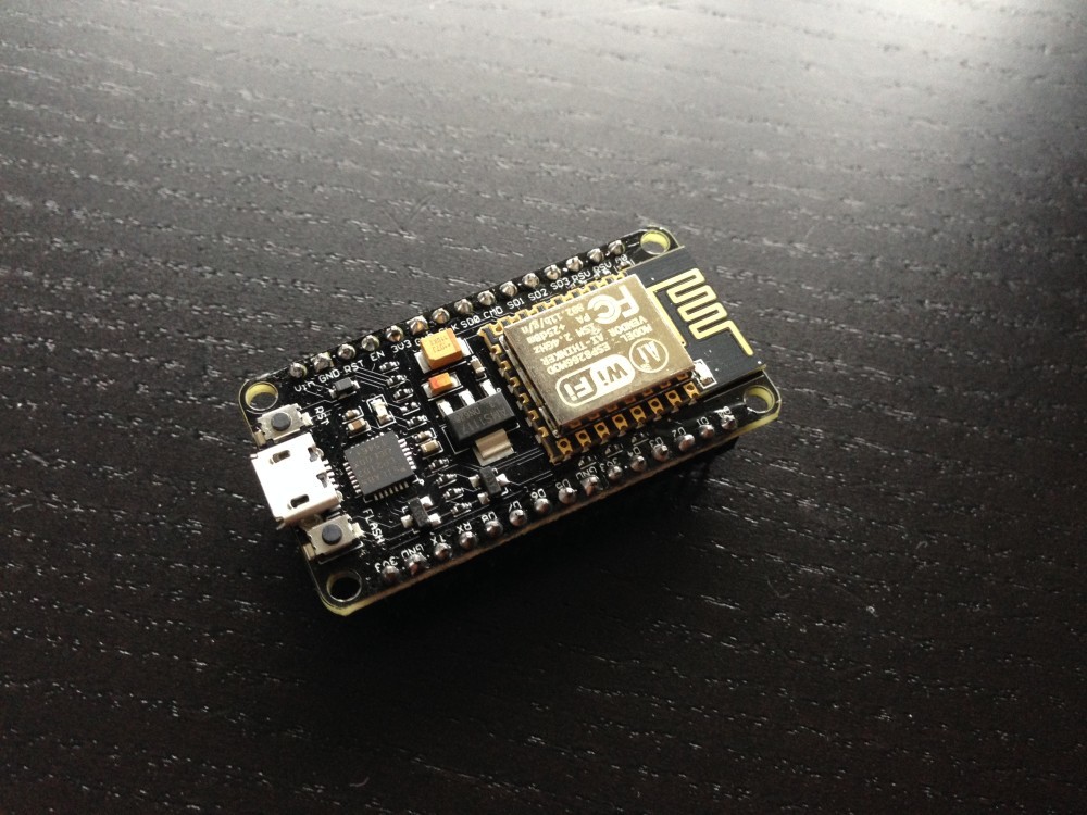
ESP8266 on NodeMCU board with a CP2102 for around 7€
Connected with MQTT
The preparations are done - I had the perfect hardware for my connected VibeLight 2.0! But I just needed an appropriate and lightweight communication protocol. I wanted to have some push mechanism to immediately let the light actors change their colors for example. At the beginning I ponder about HTTP with polling and websockets with a more native “real time” push. But both possibilities were not really satisfying for me. Fortunately I found the MQTT protocol, that was developed for IoT applications and which is very lightweight (it nearly has no overhead).
The protocol is so lightweight, that updates will be scheduled in under 1 seconds - even though the central broker server is standing somewhere in the internet. I was impressed that the scheduling time is NOT much longer despite I used mobile internet with slow EDGE (2G) network!
When you use the MQTT protocol, any amount of devices can subscribe or publish on channels. One central server (called “broker”) manages all operations. The server authenticates the devices/users also. For this project I use the free MQTT server implementation Mosquitto that is really powerful and detailed configurable. For the Arduino/ESP8266 side exists some nice MQTT libraries: I used the PubSubClient library from Nick O'Leary.
Another requirement for me as a security focused developer was the fact, that the connection between the devices and the broker is always secure encrypted. The Arduino/ESP8266 community already had a nice solution, that allows to encrypt TCP connections with TLS 1.1. However I had to modify the PubSubClient library to prevent it from any MITM attacks (by default no certificate checks are intended).
Any amount of connected light actors
Because it is possible that N clients/devices can subscribe on the same channel, you can use nearly an unlimited amount of light actors in your room/flat. When you publish on a channel (e.g. which light scene you want), each device that subscribed on this channel will be notified about the update and is able to change its light immediately. I wrote the firmware in this way, that it looks cool with light strips for indirect lighting as well as with lamps that have just a few LEDs. You can enable multiple light scenes (e.g. gradient, divided colors): the light scene defines just how the LEDs are used, the colors itself you can set always without changing the firmware.
How the hardware is build
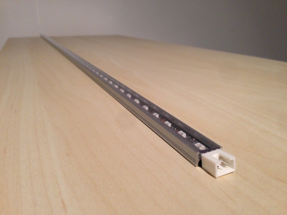
I created two light actors for my room: I updated my old 1 meter light strip and additionally I modified a normal Ikea Fado lamp to a VibeLight 2.0 light actor. These are my final light actors:
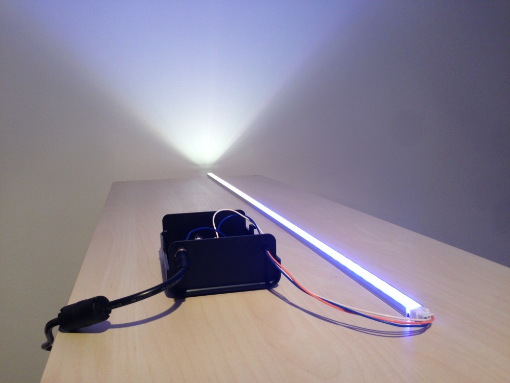
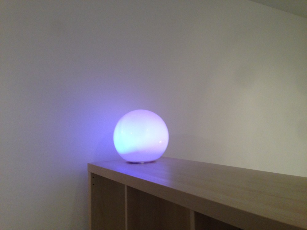
Updated light strip and modified Ikea Fado lamp with VibeLight 2.0
The opened Ikea lamp:
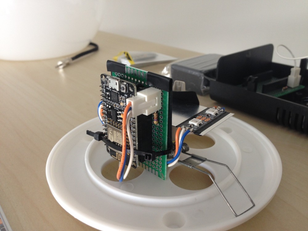
The inner parts of the modified Ikea Fado lamp
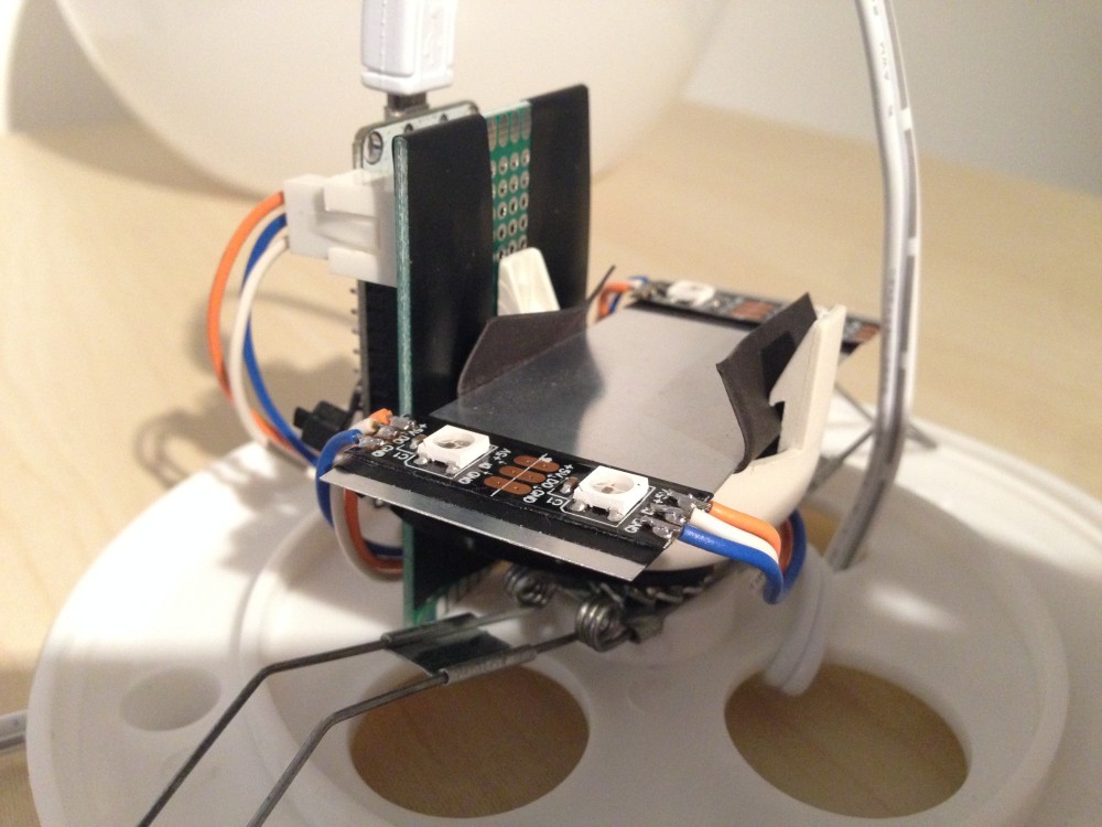
The opened light strip controller:
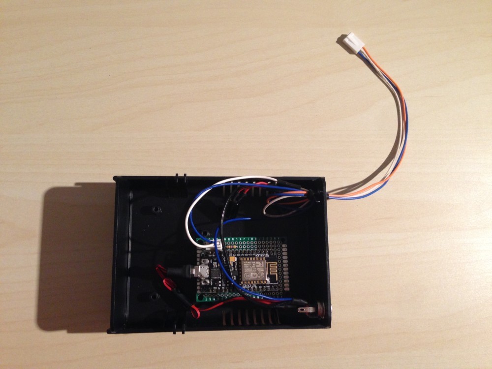
The inner parts of the updated controller and the detachable light strip
Both actors use nearly the same circuit. However the light strip controller from VibeLight 1.0 has still a 1000µF capacitor, so I don't soldered an additional capacitor on light strip controller circuit. Nevertheless on the following image, you see the complete circuit with capacitor:
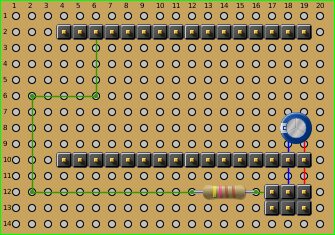
Complete circuit of VibeLight 2.0
Setup of Mosquitto
First install the package:
~# apt-get install mosquitto
Create TLS certificates
Firstly you create a key and a certificate for your certificate authority (CA). Unfortunately this is required:
~# echo "01" > "/etc/mosquitto/ca_serial.txt"
~# openssl ecparam -genkey -name prime256v1 -noout -out "/etc/mosquitto/ca.key" -outform PEM
~# openssl req -new -x509 -days 3650 -subj "/CN=VibeLight 2.0 CA" -key "/etc/mosquitto/ca.key" -out "/etc/mosquitto/ca.crt" -outform PEM
Than you create a key and a certificate for your concrete server domain:
~# openssl ecparam -genkey -name prime256v1 -noout -out "/etc/mosquitto/mqtt.sicherheitskritisch.key" -outform PEM
~# openssl req -new -subj "/CN=mqtt.sicherheitskritisch.de" -key "/etc/mosquitto/mqtt.sicherheitskritisch.key" -out "/etc/mosquitto/mqtt.sicherheitskritisch.csr"
~# openssl x509 -req -days 3650 -CA "/etc/mosquitto/ca.crt" -CAkey "/etc/mosquitto/ca.key" -CAserial "/etc/mosquitto/ca_serial.txt" -in "/etc/mosquitto/mqtt.sicherheitskritisch.csr" -out "/etc/mosquitto/mqtt.sicherheitskritisch.crt"
Important: The value mqtt.sicherheitskritisch.de in the commands above are adapted for my server and need to be changed to your environment of course.
Now you output the SHA1 fingerprint of your certificate for a later step:
~$ openssl x509 -in /etc/mosquitto/mqtt.sicherheitskritisch.crt -outform DER | sha1sum | cut -c 1-42 | fold -w 2 | paste -s -d ' '
The command should output something like:
57 36 77 fe e4 3e a9 ae c2 3c 33 dc 60 82 56 18 18 4d 60 50
Modify the configuration
Now you change the configuration file /etc/mosquitto/mosquitto.conf to this:
bind_address mqtt.sicherheitskritisch.de
port 8883

pid_file /var/run/mosquitto.pid
log_dest file /var/log/mosquitto/mosquitto.log

persistence true
persistence_location /var/lib/mosquitto/


cafile /etc/mosquitto/ca.crt
certfile /etc/mosquitto/mqtt.sicherheitskritisch.crt
keyfile /etc/mosquitto/mqtt.sicherheitskritisch.key

## The cipher "AES256-SHA" is the highest cipher that the ESP8266 supports
ciphers ECDHE-RSA-AES256-GCM-SHA256:ECDHE-RSA-AES128-GCM-SHA256:ECDHE-RSA-AES256-SHA256:ECDHE-RSA-AES128-SHA256:ECDHE-RSA-AES256-SHA:ECDHE-RSA-AES128-SHA:AES256-SHA

## The ESP8266 supports only TLS 1.1 or below
tls_version tlsv1.1


allow_anonymous false
password_file /etc/mosquitto/passwd


## Include other configurations /etc/mosquitto/conf.d/*.conf
include_dir /etc/mosquitto/conf.d
The parameter bind_address must be set to your server's public IP address or domain. Additionally the values of certfile and keyfile must be changed to the path of your created TLS certificate and key.
Than you create two MQTT user accounts:
~# mosquitto_passwd -U /etc/mosquitto/passwd bastian
~# mosquitto_passwd -U /etc/mosquitto/passwd device_abcdefghijklm
The first user bastian will be used later as the user account in the app, the second user device_abcdefghijklm will be your first light actor. Be sure you choose different passwords for each user!
Now you restart Mosquitto:
~# systemctl restart mosquitto
Flashing the firmware
The firmware is flashed via the Arduino IDE to the ESP8266. How you prepare the Arduino IDE for the ESP8266 hardware is described on many places on the internet. Thus, I don't will explain it here again. For the NodeMCU I used the following flash configuration in the Arduino IDE:
| Value | |
|---|---|
| Board: | NodeMCU 1.0 (ESP-12E Module) |
| CPU Frequency: | 80 Mhz |
| Flash Size: | 4M (1M SPIFFS) |
| Upload Speed: | 115200 |
But before you flash the firmware, you need to change some values in the firmware to your environment:
#define WIFI_SSID                   "YOUR_WIFI_SSID"
#define WIFI_PASSWORD               "YOUR_WIFI_PASSWORD"

#define MQTT_CLIENTID               "Vibelight Device 1.0 xxxxxxxxxxxxx"
#define MQTT_SERVER                 "mqtt.sicherheitskritisch.de"
#define MQTT_SERVER_TLS_FINGERPRINT "57 36 77 fe e4 3e a9 ae c2 3c 33 dc 60 82 56 18 18 4d 60 50"
#define MQTT_PORT                   8883
#define MQTT_USERNAME               "device_abcdefghijklm"
#define MQTT_PASSWORD               "YOUR_MQTT_PASSWORD"

...

#define NEOPIXELS_COUNT             60
First you change the values of WIFI_SSID and WIFI_PASSWORD to your correct Wifi credentials, to make sure, the ESP8266 is able to communicate with the internet. The 'x' placeholders of MQTT_CLIENTID should be changed to any random alpha numeric value. The value MQTT_SERVER is the public available IP address or domain of your MQTT broker and in the line MQTT_SERVER_TLS_FINGERPRINT you copy the SHA1 fingerprint of your server certificate, you output earlier. Last but not least, you enter the appropriate MQTT user credentials in the lines MQTT_USERNAME and MQTT_PASSWORD.
Important: For each device, you must enter a different MQTT user account and a unique client ID, if you want to have both devices running at the same time! Otherwise the authentication of both devices will not work!
Finally you enter the correct amount of WS2812/Neopixels for each light actor in the line NEOPIXELS_COUNT.
First test
If the flash process is done, you can test your light actor. I recommend to activate the serial monitor to see the output of your device (nice to debug errors like invalid credentials etc.). For easy MQTT testing, I recommend to use the package mosquitto-clients: it contains the useful command line program mosquitto_pub:
~$ mosquitto_pub -h mqtt.sicherheitskritisch.de -p 8883 \
    -u "YOUR_MQTT_USERNAME" \
    -P "YOUR_MQTT_PASSWORD" \
    --tls-version tlsv1.1 \
    --cafile /path/to/ca.crt \
    -t '/vibelight/api/1.0/' \
    -m '2A92CCECE2C2C'
With the command above, you enable light scene 2 (divided colors) with the colors 0xA92CCE and 0xCE2C2C on all of your VibeLight 2.0 actors, that are connected (parameter -m with 2A92CCECE2C2C).
Important: Like always you need to change the address of your broker and the parameter --cafile needs the path to a copy of the file /etc/mosquitto/ca.crt you created in the step “Create TLS certificates”.
Install the iOS app
First you need to install “Cocoapods” (the installation should be decribed on the official website). Open the workspace src/Client (iOS)/VibeLight/VibeLight.xcworkspace with your Xcode (I worked with version 7.3.1). Probably you need to configure your developer signing certificate as well. After that you should be able to deploy the app to your iOS device and start it.
Required modifications
Some values in the app are currently hard-coded:
- The IP address/domain of the MQTT broker in the file
MQTTConnection.swift - The root certificate of the CA (currently the file
VibeLight/Resources/KlosterTrust_Root_CA.crt) and referenced also in the fileMQTTConnection.swift. Here you need a copy of the file/etc/mosquitto/ca.crtyou created in the step “Create TLS certificates”.
These values you need to change to your conditions.
The constraints in SettingsViewController are not set correctly, thus the input fields are not proper centered. Because I don't have a MacBook at the moment, I can't fix ;-)
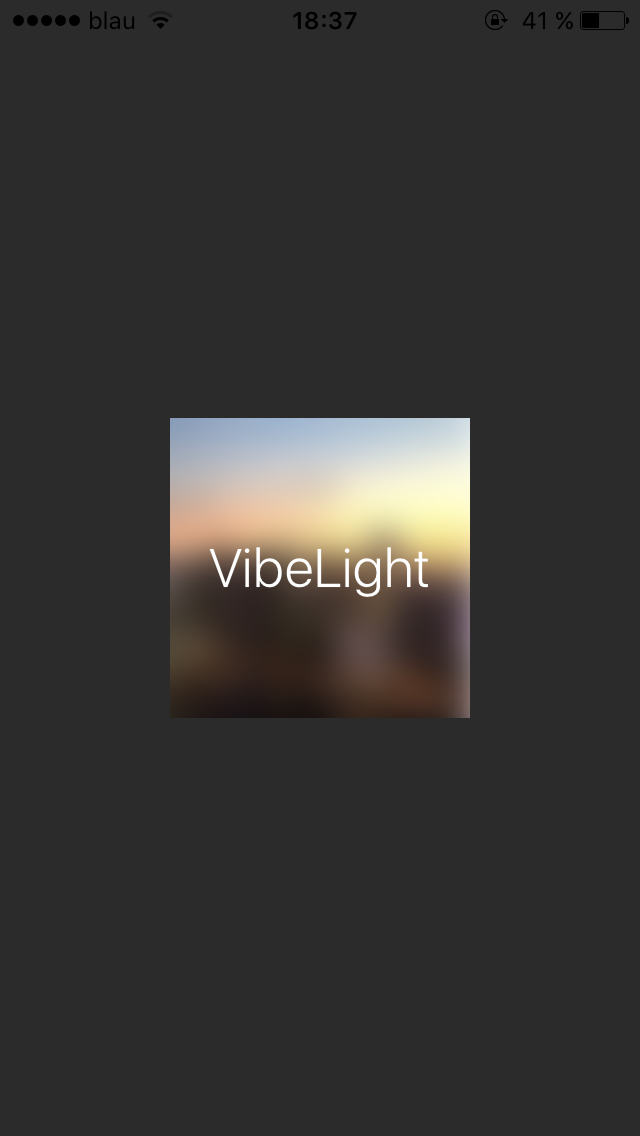
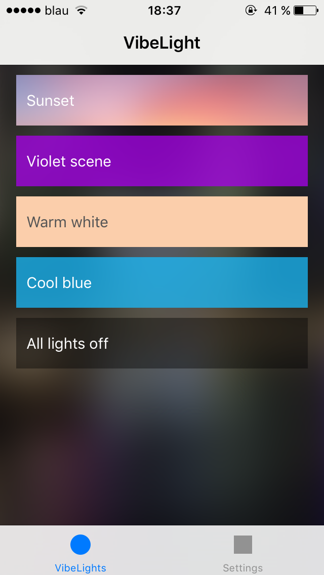
Here you can see some screens of the app:
Have fun with the project :-)
Source code available on Github
The library is available on Github:
Tags: App, LED, WS2812B, ESP8266, DIY, Internet of Things, IOT, MQTT