Build your own smart Wi-Fi button for 9€
Written by Bastian Raschke.
Published 2017-03-30 in the category Smart Home.
For my OpenHab smarthome setup in my room I needed some physical switches to avoid to always need to unlock my phone, start the app, wait until its connected and finally turn on the lights. I use OpenHAB because I have a mixed setup with a lot of Philips Hue bulbs and also some DIY lightstrips which are connected via a ESP8266 and receive their commands via MQTT from my broker. Thus I can't simply use Philips Hue switches. Of course it is possible to grab the state of these switches via OpenHab but in my view these switches are to expensive just because it is just a switch. Other commercial Wi-Fi smart buttons cost nearly the same or more (40€+).
Finally I decided to build my own Wi-Fi buttons with ESP8266...
Inspired by an article in the c't magazine (2017-02) and this project I planned my own buttons. But there was one big problem regarding all these “push light” projects: The used push lights are one of the most poor quality products I ever seen. They look shitty, especially when you ordered silver buttons like me. I re-painted them to white to have a better “smart devices” look and feel. To sum up, it was really a pain in the ass, the plastic was fragile as fuck and the final re-painted button looked still shitty.
I need better quality
So, I needed better products, so I ordered some better buttons from Sycees on Amazon. These buttons costs more (around 14€ for 3 pieces) but have a reasonable quality and look really cool:

The buttons from Sycees have a good quality
Build the button
1) Preparations
There is one big difference between the “push light” buttons and the new buttons: They have no physical switch to reset the ESP8266 after deep sleep. The circuit uses capacitive sensing to detect a “push”. Because the used touch IC on the board was designed only to control/dimm LEDs and not suitable for me to have a pulled up switch that goes down if you touch the capacitive area. Thus I ordered a bunch of TTP223 based mini touch boards on Ebay. Be sure you order a board that allows to change the output mode: We need the “active low output” mode (TOG=0 and AHLB=1) that means the output is pulled up until we touch the capacitive area (see the datasheet on page 4). Furthermore I removed the on-board LED to avoid a red light when pushing.
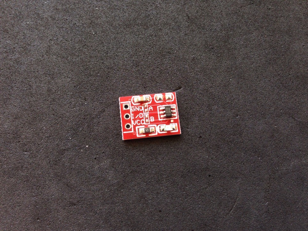

We need to connect the solder bridge “A” to have “active low output” mode and remove the on-board LED
I also removed the on-board LED on the ESP01 board to save energy:
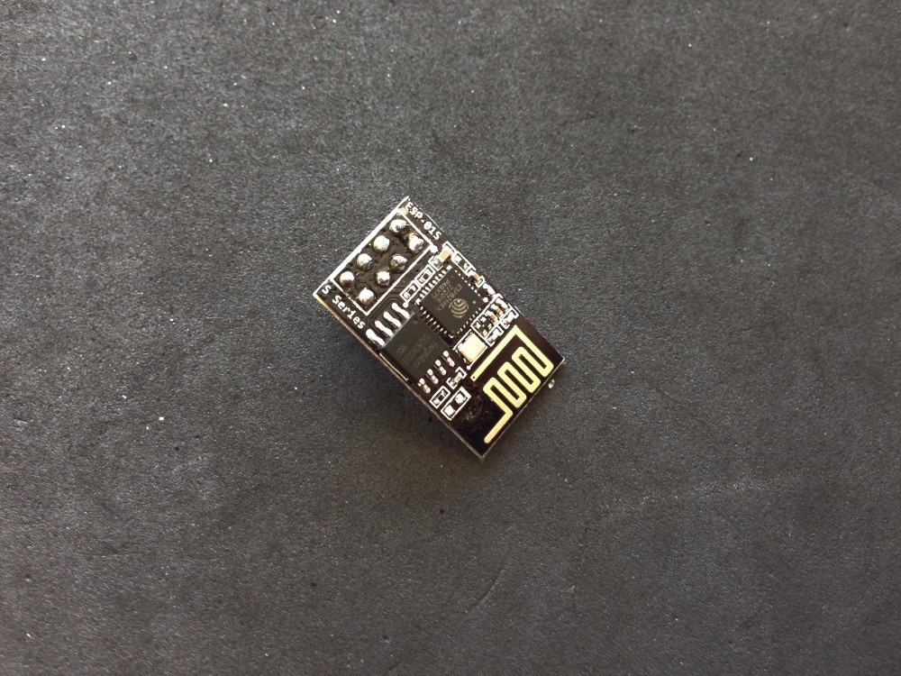
ESP01 with removed on-board LED
2) Remove circuitry of Sycees buttons

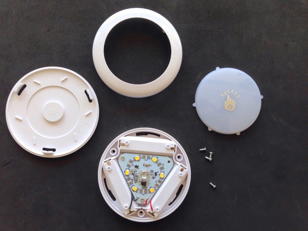
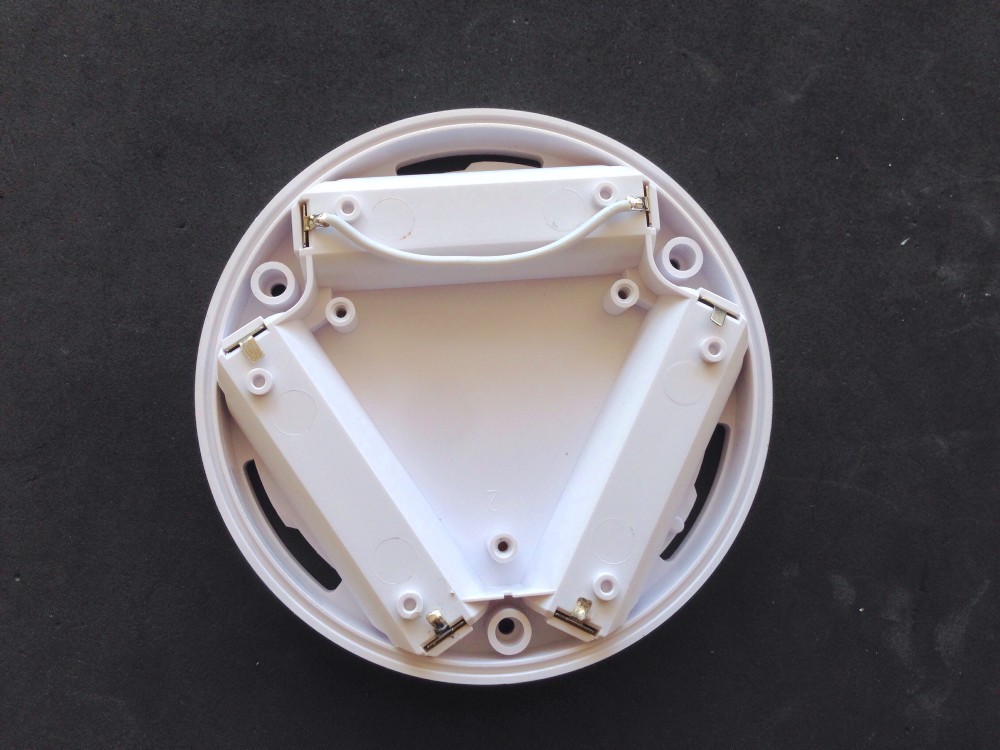
The opened Sycees button with all included components
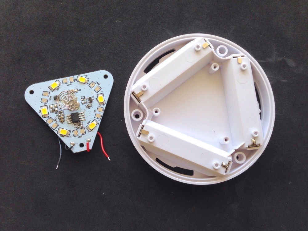
The Sycees button with desoldered circuit board
3) Bypass one battery
We need to add a short wire to bypass the third battery:
The soldered wire to bypass the third battery
Warning: Never put a battery in this slot afterwards to avoid short it!
4) Install the step-up converter
Because the voltage of two rechargeable batteries is 2,4V that is not enough for a ESP8266, we need a step-up converter, that converts the voltage to 3,3V. I used the converter U1V11F3 from Pololu that has a good quality and works with currents up to 1,2A that is more than enough for a ESP8266.
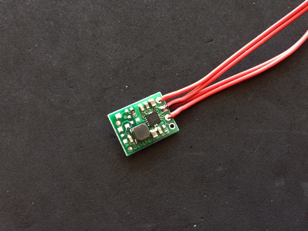
The step-up converter installed in the button case
5) Solder the LED
For the status, I used a low-power green LED with suitable resistor:
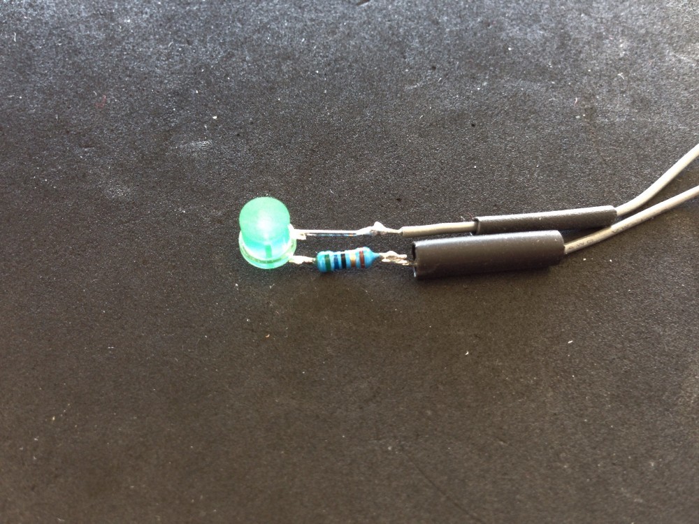
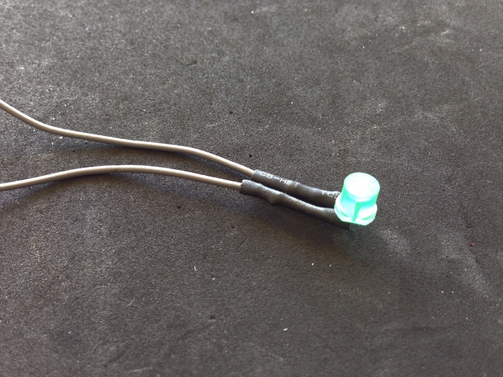
The LED with heat shrink tube (sorry for bad picture quality)
I cut the round top side of the LED with a saw to have a plane surface to glue it easier.
6) Basic setup for ESP01
I needed to add the common ESP01 minimal setup pull-up/down resistors. I used to normal wired 10kOhm resistors and one small SMD 10kOhm resistor to avoid too many wires.
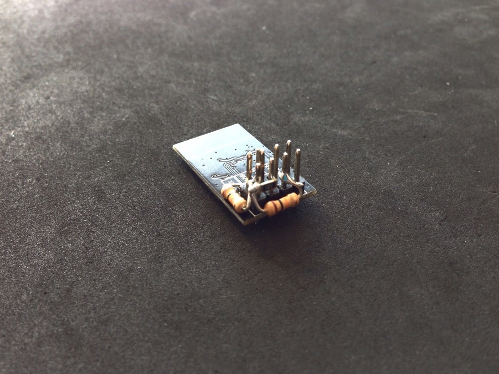
The minimal ESP01 resistor setup
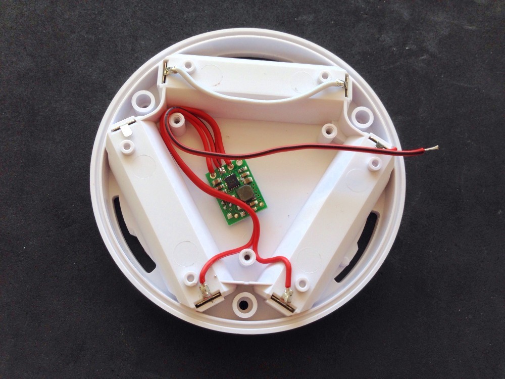
7) Connect all components

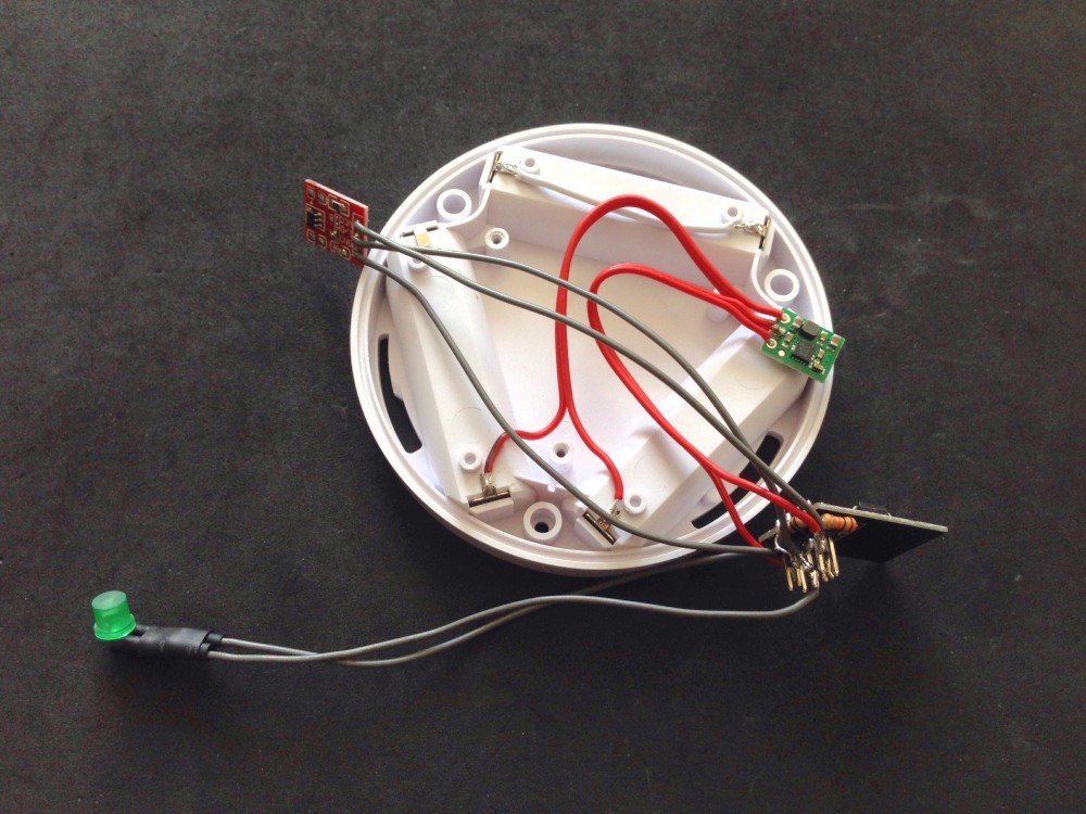
The connected components in the button case
8) Flash the firmware
Now I flashed the firmware to the ESP01. It is a bit annoying to connect the IO-0 port to ground when power up the ESP01 to let it start in boot mode instead of running the firmware. But this is just a first world problem ;-)

The USB serial converter connected to the ESP01
9) Glue the LED and the touch board
Finally we glue the LED and the touch board to the top of the button case. I used hot glue and positioned the LED exactly under the power symbol of the Sycees button.
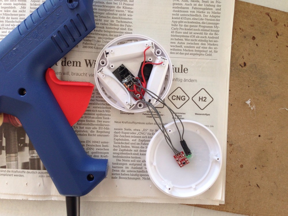
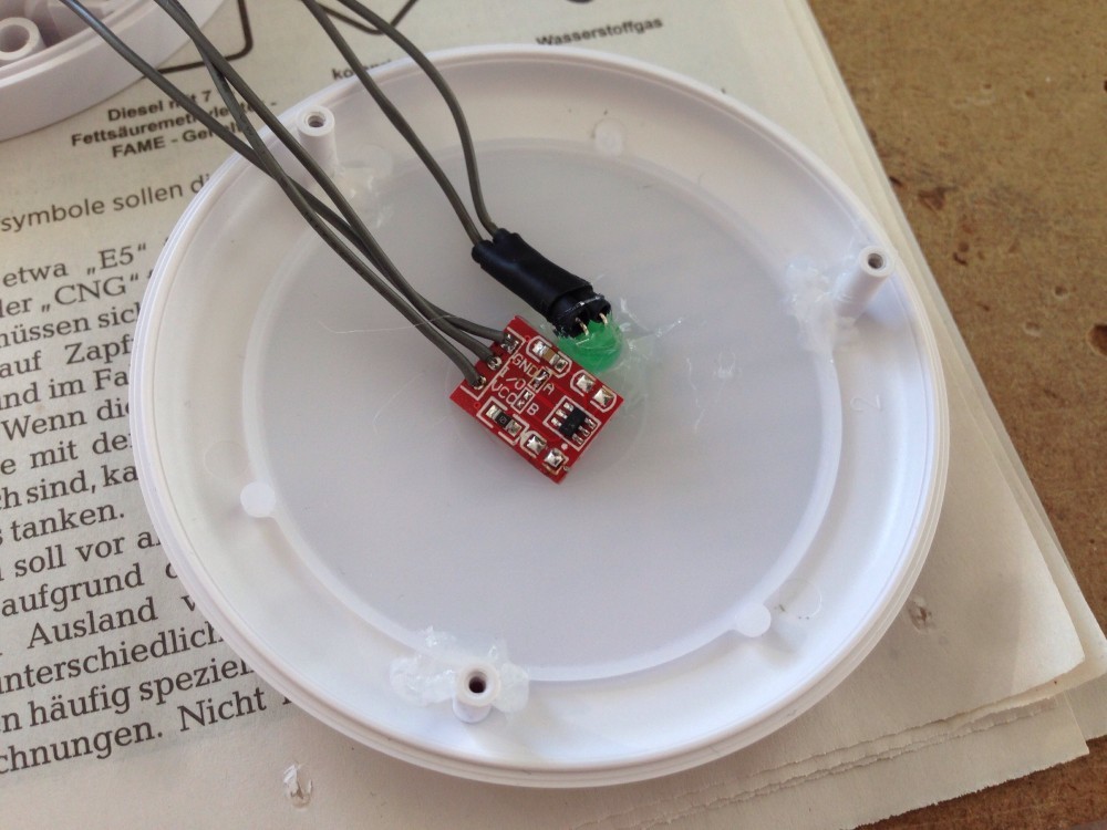
The LED and the touch board are glued with hot glue
And we are done
After these steps we are finally done and can test our button:
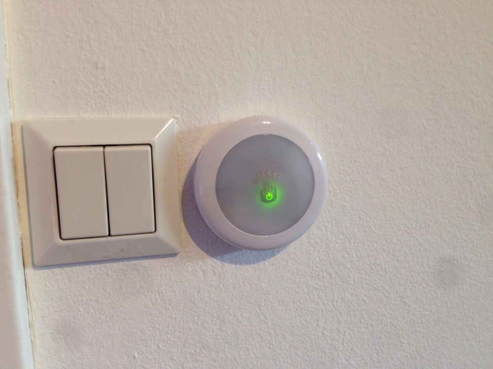
The smart button beside a conventional switch - enjoy the dust on my iPhone lens ;-)
The firmware
The firmware is available on Github.
Have fun with it :)