Professional electric cruiserboard (DIY) controlled with modified Wii Nunchuck
Written by Bastian Raschke.
Published 2017-04-16 in the category Skateboard.
When I took my pennyboard with me, people often saw the technical upgrade under the board and asked me if the board has a motor. I always had to answer No, it has only light and Wi-Fi - but these comments challenged me... Additionally Nils motivated me that I need an electric board for sure. So I started to build one.
It took a lot of time (more than 3 months) and cost a lot of money. I ordered a “Single Motor Mechanical Kit” from DIY Electric Skateboard which was not to expensive (relative to other products) and seems to be good quality. Additionally I ordered the motor, the VESC and some other small parts from there. Unfortunately (for me) the shop ships from San Francisco, so I waited around 1-2 weeks and had to pay taxes and duty in Germany. Finally the quality was quite nice (except for the very poor bearings). I really recommend these parts and this shop. For a German as me it was a bit scary that on the page was no real imprint or address of the company. But I payed with Paypal, so felt safe and finally the shop was respectable.
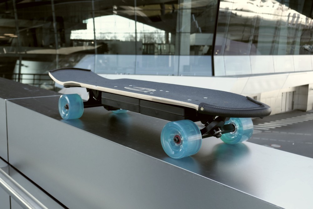
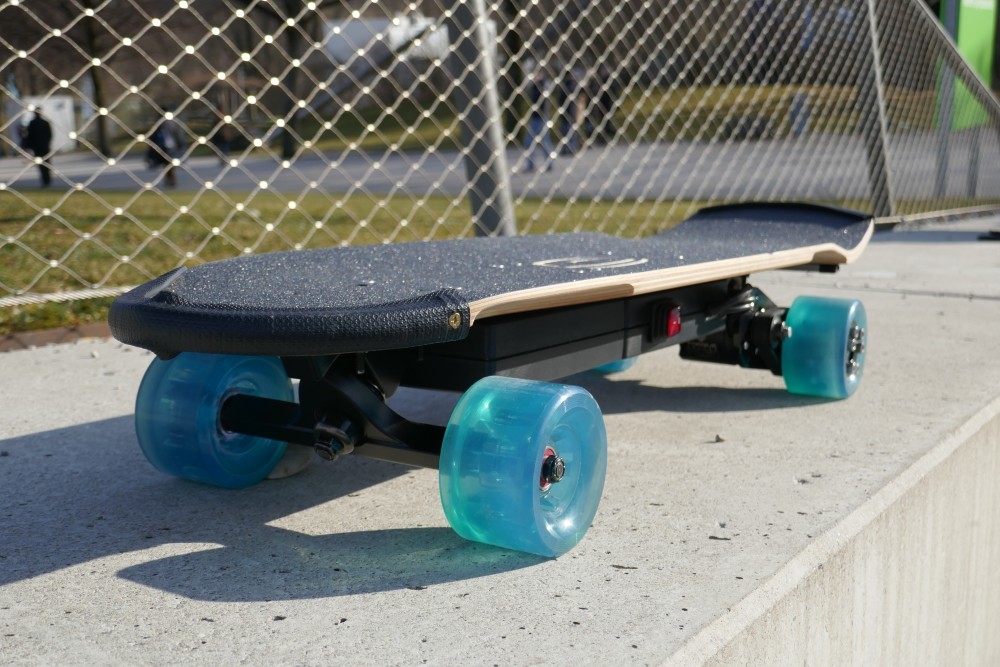
For this project I put in a lot of sweat and love to have a professional result. But checkout by yourself:
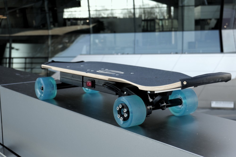
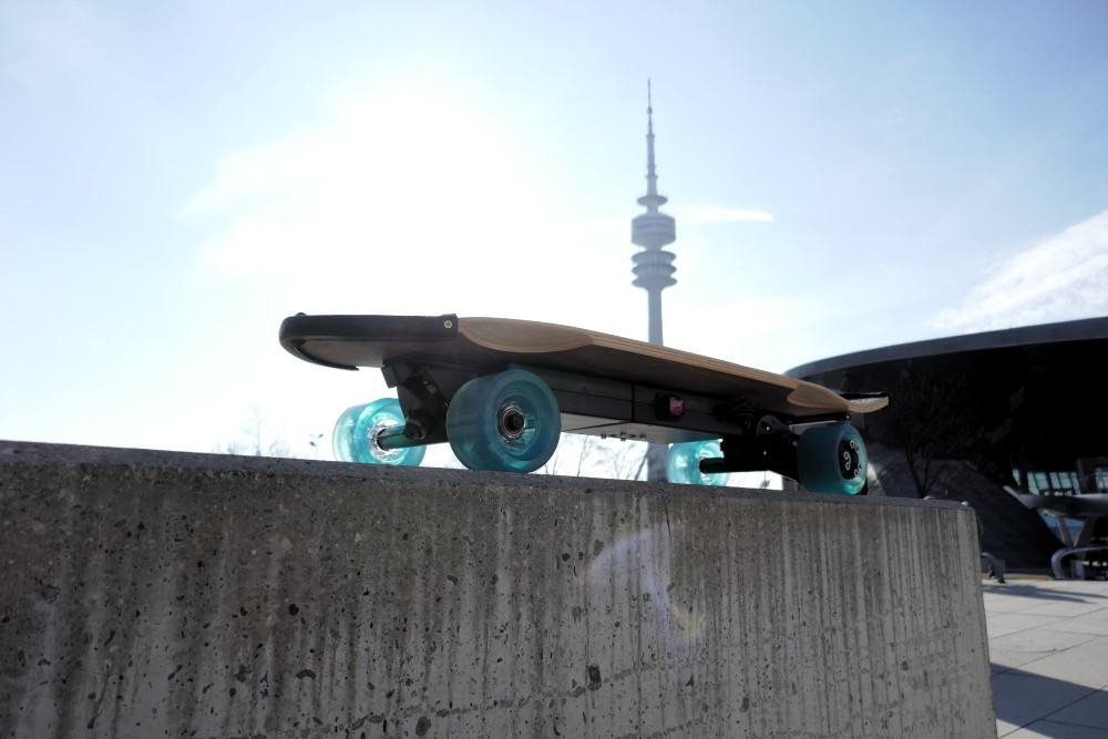
The board in front of the modern BMW world building in Munich
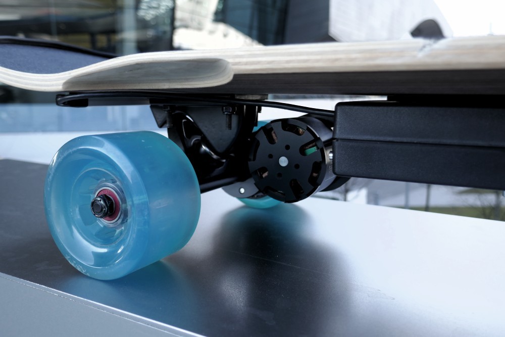
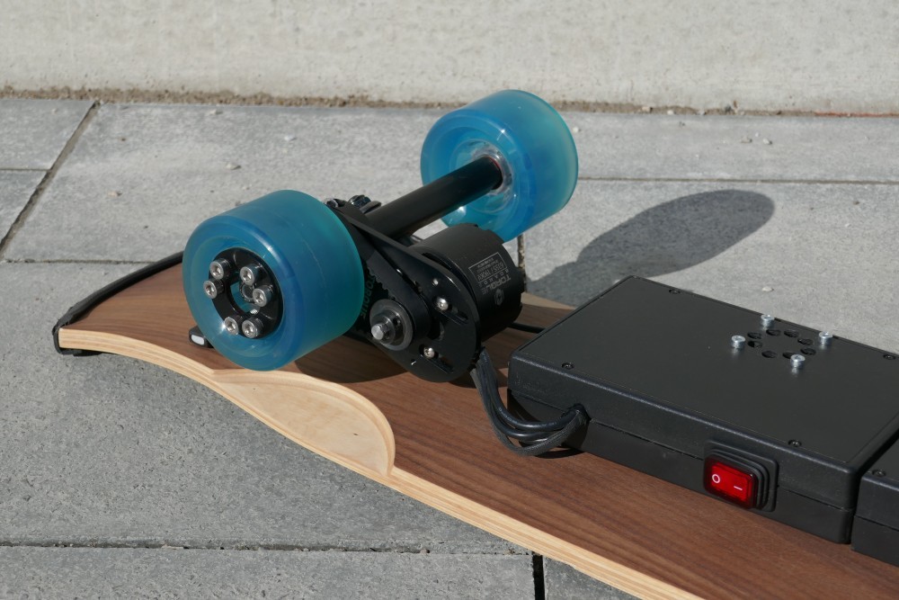
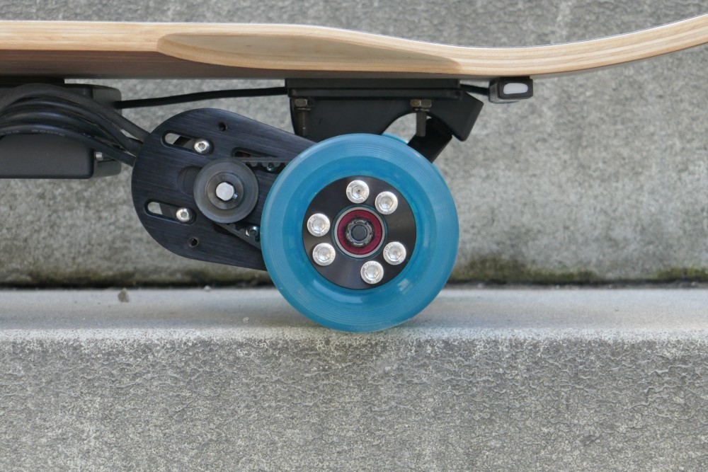
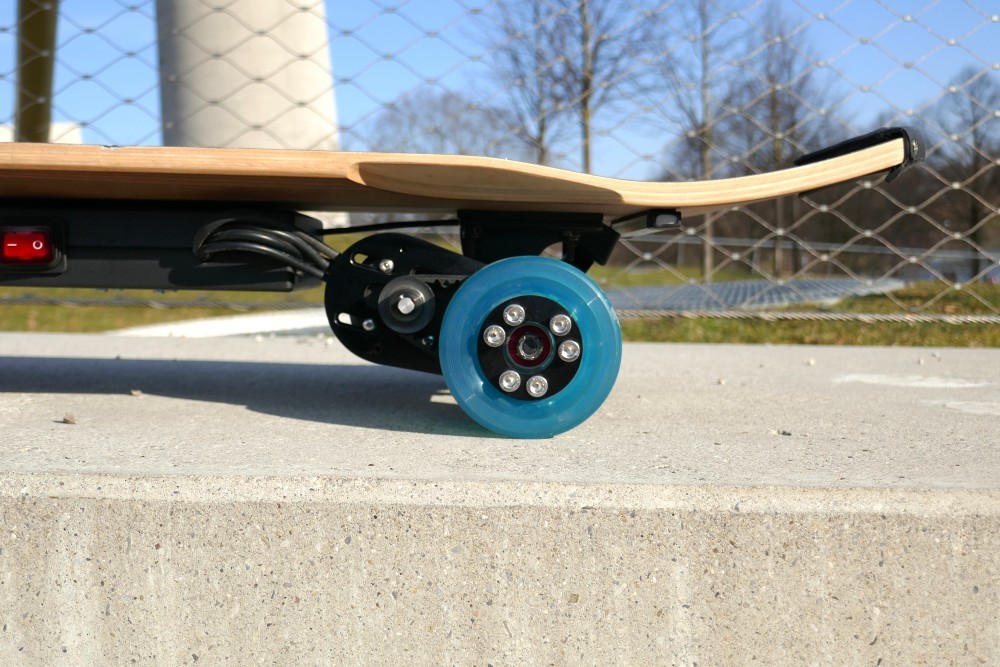
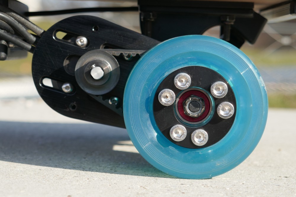
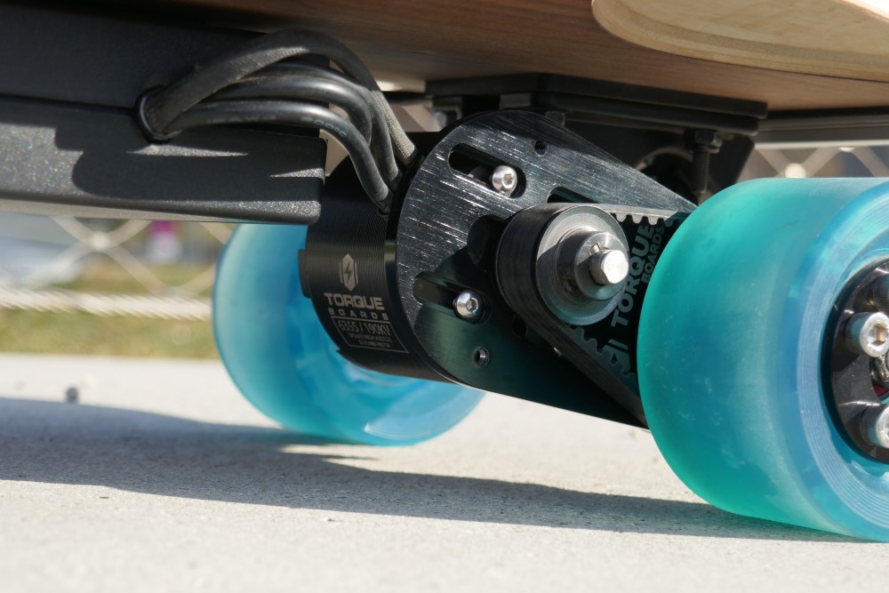
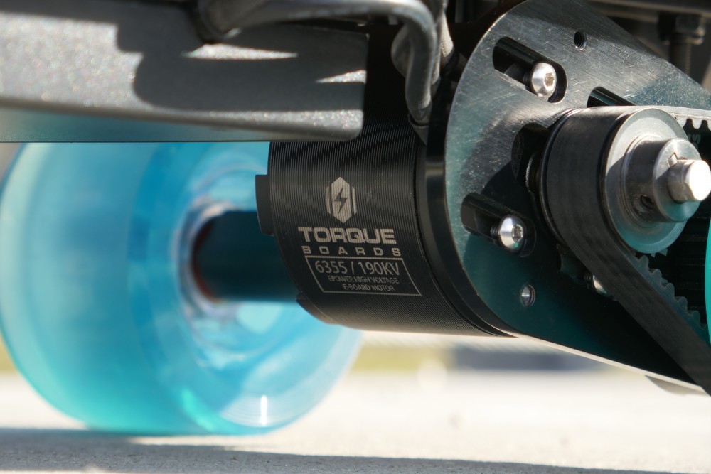
The powerful 6355 190KV brushless motor has an insane startup torque
Features
The board has a lot of awesome features. See the most important:
- depending on setup speed around 24km/h is possible
- distances around 15 kilometers are possible (also depending on setup and driven speed)
- the board is controlled with wireless modified Wii Nunchuck
- provides a Wi-Fi access point to be monitored by smartphone (motor temperature, MOSFETs temperature, battery level of board and Nunchuck, consumed/produced energy)
- RGB-LED strip at the end of board for individual backlight (controllable via smartphone)
- using the ESP8266 in board (NodeMCU) and Nunchuck controller (Adafruit Feather HUZZAH)
- OTA firmware updates possible
The remote (Nunchuck)
The board is controlled by a Nintendo Wii Nunchuck which I bought on Ebay for around 10€ (used, but in good condition). I preferred an original one from Nintento to be sure having good quality. But the controller was wired which is quite unfavorable for an electric cruiserboard. Therefore I needed a wireless solution.
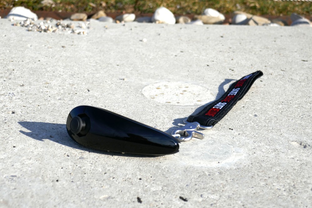
The remote is a modified Nintendo Wii Nunchuck
In the first place I wanted to avoid RC car technology cause it is not encrypted and I have no control over the protocol. Thus I built a complete DIY solution. I cut the wire of the Nunchuck, bought a Adafruit Feather HUZZAH (which is basically a ESP8266 with a Li-Po battery jack and charging circuitry). Then I removed a lot of contained plastic to create more space for all parts. When using the Nunchuck with the Nintendo Wii, the joystick position (X and Y axis), the button states (Z and C button) and the acceleration sensor values of the Nunchuck are transferred via I²C. So it's easy for us to receive the data on the ESP8266.
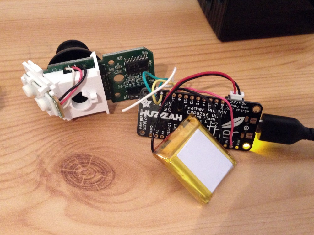
The opened Nintendo Wii Nunchuck and the Li-Po battery (photo without battery sensor)
The Adafruit Feather in the modified Nunchuck is powered by a 400mAh Li-Po battery. The ESP8266 consume a lot of energy (peaks of 250mAh are possible). Thus the energy capacity of the battery lasts only for around 1-2 hours. The problem was the limited space in the modified Nunchuck: There is not so much space to put a Adafruit Feather, wires and also a big battery pack ;-) But I think the time is okay for my propose. If you want, you can power and/or charge the Nunchuck via a USB powerbank if you run out of energy.
UDP - fast and simple
I chose UDP for the communication because I needed a fast protocol without a lot of overhead. The packets have to be sent quick and periodic, I don't need a 3-way handshake like used in TCP. If a packet is lost or dropped, it is no problem. I send 10 packets per second. I set the failsafe timeout of the VESC to 500ms, so if the packet is lost 5 times or more, the motor throttle is stopped automatically and the VESC sets the board to running idle (it would be possible to break automatically but I preferred just running idle).
The data packet format
The data packet format is quite simple. I send 5 values in 4 bytes:
- the X axis value (8 bit)
- the Y axis value (8 bit)
- the state of the Z button (1 bit)
- the state of the C button (1 bit)
- the battery voltage (float value is multiplied with 10) (8 bit)
For example one packet:
1111 1111 0000 1111 1000 0000 0010 1010
The following example data is contained:
| Value (binary) | Value (decimal) | |
|---|---|---|
| X axis | 1111 1111 | 255 |
| Y axis | 0000 1111 | 15 |
| Z button state | 1000 0000 | 1 |
| C button state | 1000 0000 | 0 |
| Battery voltage | 0010 1010 | 42 (42 / 10 = 4,2V) |
Tweak and transfer the data
The UDP packets are transferred via Wi-Fi. So when start the remote, it tries to connect to the configured Wi-Fi network. When the connection was successful, it starts to send 10 UDP packets per second to the board, which has a static IP address. The analog joystick axis theoretically should depict values from 0 to 255. In reality the values are not exact these values. So it is possible to configure the real limits to tweak the joystick to send “perfect” values (the board firmware expects perfect values from 0 to 255).
Battery level sensing
To know about the energy level of the Nunchuck I build a battery level sensor. That sounds complicated but it isn't: You just need 2 resistors and some additional wires. On the ESP8266 we have an analog input which can measure voltage from 0 to 1V. The 1 cell Li-Po battery has an maximum voltage of 4,2V. So its a lot higher and would kill the ESP8266 if you connect the battery voltage directly to this input. Therefore we need the 2 resistors for a voltage divider: We want to drop 4,2V to a value under 1V. I chose a 10kOhm and a 2,2kOhm resistor. So the voltage of 4,2V is dropped to 0.76V which is okay as a maximum. This technique is described more detailed on Adafruit page.
Basically the resulting voltage can be calculated with this formula:
Vout = R2 / (R1 + R2) * Vin
With real values we get our expected result:
Vout = 2200 / (10000 + 2200) * 4,2 = 0,76
The output of the analogRead(analogPin) return values from 0 to 1023, so I need to map it to 0-1000 (then we have millivolts). But because of the voltage divider, we need to calculate this input voltage value to the real voltage value: 1V (= 1000mV) in reality would result 0,18V (= 180mV) after voltage divider, thus we divide the value from the voltage divider by 180. Then we finally have the correct real voltage - yeahh ;-)
Firmware for Nunchuck
The firmware is available on Github:
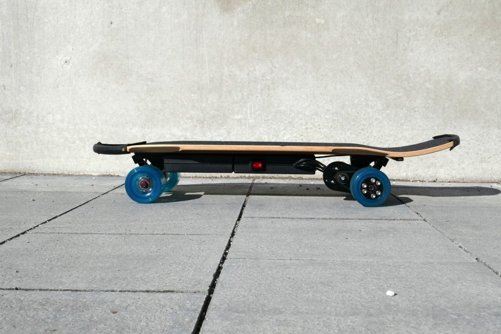
The board
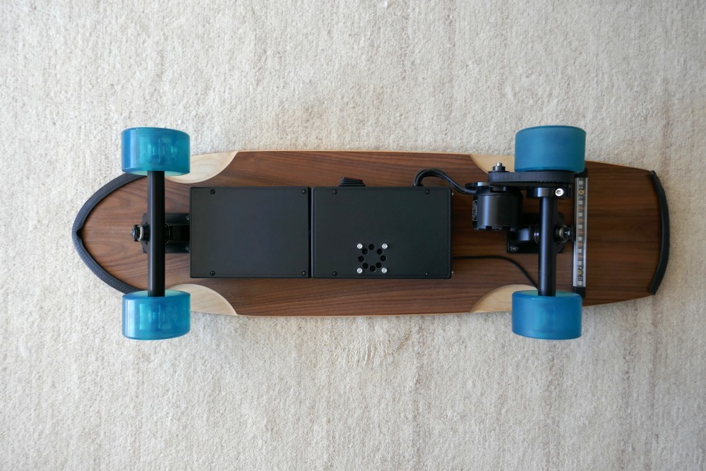
A compact hardware overview of the board:
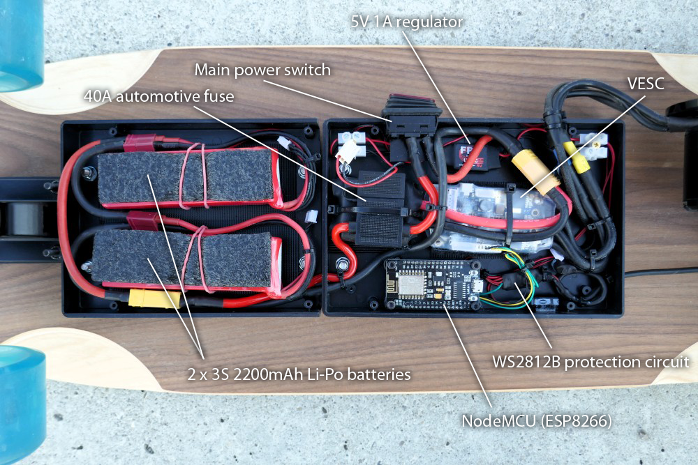
- based on a 33,4" Olson&Hekmati cruiserboard deck
- powered by a 6355 190KV brushless high performance motor with maximum power of 2500W
- brushless motor is controlled by VESC (Vedders Electric Speed Controller) with regenerative braking
- using a 6S lithium polymer battery setup (two 3S batteries in serie à 2200mAh or 5500mAh)
- 8 powerful WS2812B RGB-LEDs for backlight
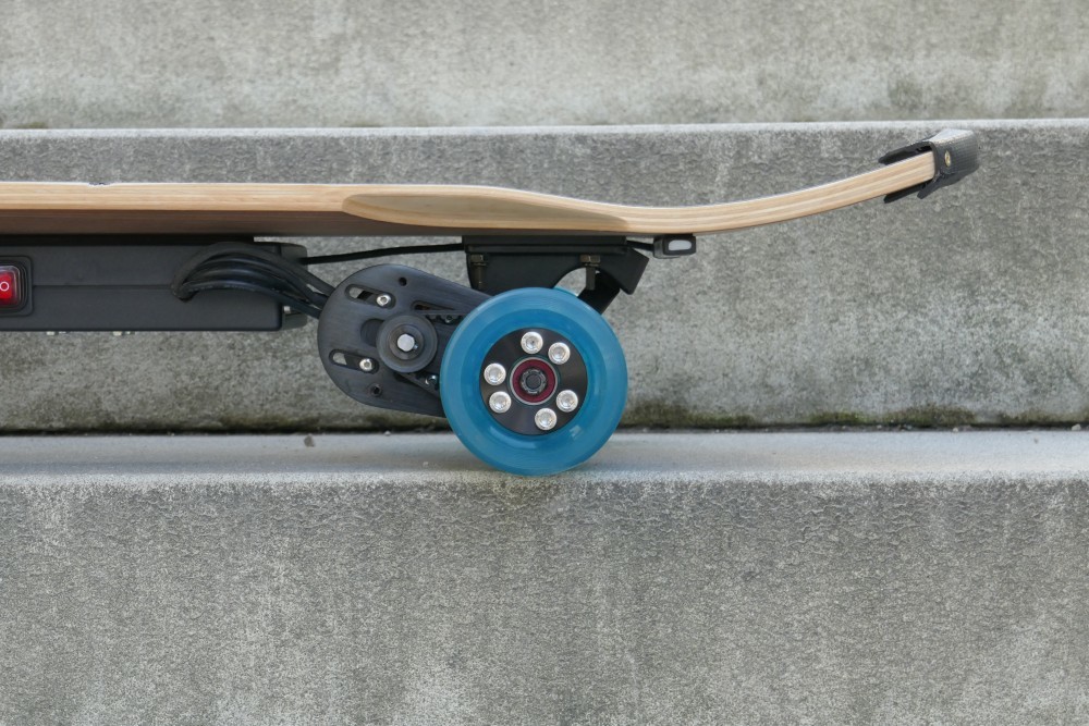
- high quality Bones “REDS” bearings
- total costs around 800€
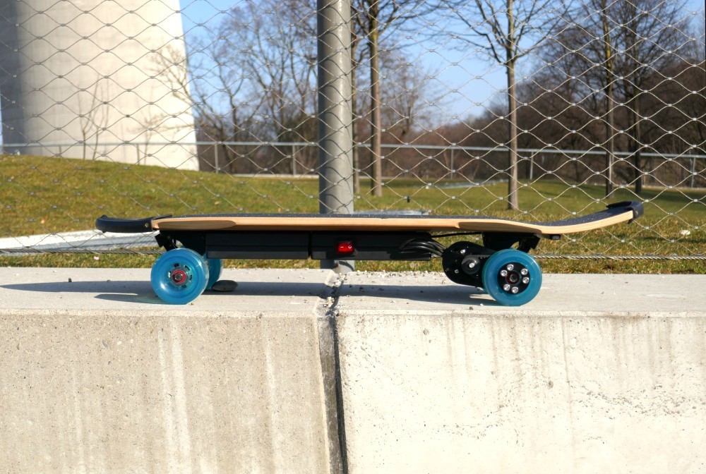
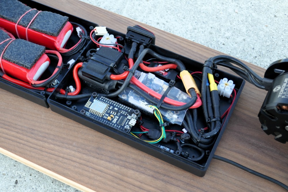
The board was really fun to build, but took the most time. A lot time I was working on the firmware and I was permanently improving the hardware. I use 2 universal plastic boxes: The first for the batteries and the second one for the electronic components. The two 3 cell batteries are connected in parallel to have a voltage of around 23V. The system is protected via a 40A fuse from a car which is connected in the main power circuitry. The power switch is connected in the same circuitry and turn on/off the complete system. For the complete main power circuitry I use 6mm copper cables to be sure they can handle the high currents.
Problem with the VESC 5V regulator
I build two power rails: The first is unregulated (which means it is directly connected to the batteries) and the second rail is 5V regulated via an linear regulator used for multicopters (it provides around 1A current). I need the 5V rail for the NodeMCU and the WS2812B LEDs of course. The VESC also provides a 5V rail which I used before, but I noticed that the specified limit of 1A is not acceptable in the reality:
The coil on the VESC gets freaking hot (more than 80°C I guess) and began burning the heat shrink tube of the VESC... Furthermore I'm sure I never reached the specification of 1A (let calculate lavishly to be sure: 300mAh for the NodeMCU and 8 * 60mAh are just 0,78A). Therefore I need to use an external regulator for the 5V rail.
The case fan cools down the VESC
On the unregulated rail I connected an additional switchable regulator for the case fan. I was sure it is not a good idea to have high power circuitry in a closed box without any air circulation ;-) So the speed of the small fan is regulated via a small potentiometer to have an adjustable compromise between air flow and noise.
The communication with the VESC
The NodeMCU receives the control commands from the Nunchuck remote and need to speak to the VESC to control the motors. The VESC provides a lot of options to communicate with: A common RC PWM signal, analog values (ADC) and UART. I chose UART because a serial connection is really easy for the NodeMCU without possible timing problems like PWM. Furthermore I was able to receive status data from the VESC (temperatures, energy monitoring, etc.). There were some Arduino compatible libraries to communicate with the VESC, but all of them had some problems in my mind: Some consisted of bad code (unmaintainable and hard to understand because of missing comments and magic numbers) and others had missing features (not all available information from the VESC was read out). So I developed my own small and clean implementation and released the libraries some month ago:
The library implements the full API that the VESC provides. It is well written, commented and easy to understand (I hope so). Write me an email if you don't understand anything ;-)
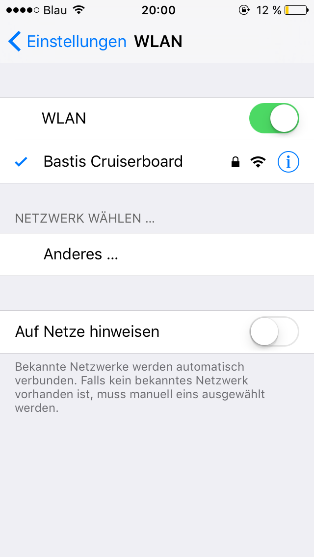
Information on smartphone via Wifi
If you want to know the battery level of the board and/or the remote, just connect it to the Wi-Fi access point of the board and open the address http://10.0.1.1. Then you see a lot of interesting information:
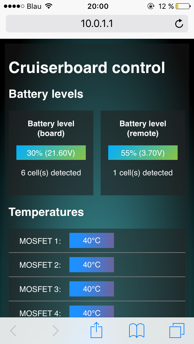
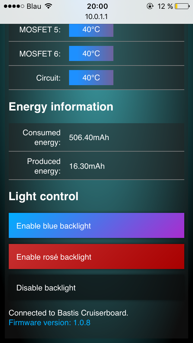
The web interface provides a lot of interesting information
Additionally you can control the backlight with your smartphone. Updates over the air (OTA) are provides as well.
Configuration of the VESC
The VESC can be programmed via a really powerful tool provided by Benjamin Vedder as well: The BLDC Tool
It is insane how many settings you can configure compared to a poor programming card of other ESCs. You can set hundreds of settings according the motor current, motor type, battery pack, battery type; you can read out real time data from the VESC (RPM, current, temperatures, voltages). The data is visualized via an beautiful chart.
Configuration for a 6S battery setup
You need to connect to VESC with the Li-Po battery first. After that you connect the mini USB cable to your computer! This order is really important to work! Than choose your VESC on the right side of the window (“Serial Connection”) and click “Connect”. Wait some seconds the tool confirms the connection with a green label on the lower right edge. Than click on “Read configuration” to set the actual values from the VESC in the tool.
In my case I just change the most important values for my setup:
Current limits
Tab “Motor configuration” > “Motor” > “Current Limits”:
| Setting | Value | Description |
|---|---|---|
| Motor max | 39,00A | Maximum allowed motor current (limited cause of the 40A fuse) |
| Motor min (regen) | -39,00A | Maximum allowed motor braking current (limited cause of the 40A fuse) |
| Batt max | 39,00A | Maximum allowed current that is took from the battery. Be sure the battery can handle the given current! But RC Li-Po batteries normally can handle a lot of load. For example the limit of my small 2200mAh batteries is 66A (they are rated with 30C discharge rate that means 2,2Ah * 30C = 66,6A). The value is limited cause of 40A fuse. |
| Batt min (regen) | -6,60A | Maximum allowed current that is used to charge the battery when braking. Be sure the battery can handle the given current! My small 2200mAh battery pack is specified to 6,6A (they are rated with 3C charge rate that means 2,2Ah * 3C = 6,6A). |
Voltage limits
Tab “Motor configuration” > “Motor” > “Voltage Limits”:
| Setting | Value | Description |
|---|---|---|
| Battery cutoff start | 21,00V | Upper voltage limit the VESC starts to limit the power of the motor to save the Li-Po battery. This value is calculated easily for a 6S Li-Po battery setup: 6 * 3,5V = 21V |
| Battery cutoff end | 19,20V | Lower voltage limit the VESC shuts down the the motor to save the Li-Po battery. This value is calculated easily for a 6S Li-Po battery setup: 6 * 3,2V = 19,20V |
Motor type
Of course we set the “Motor Type” to “BLDC”. Optionally you can set some reasonable temperature limits.
Click on “Write configuration” to write the new values to your VESC.
Initial motor detection
This step is really important, because otherwise the motor runs really poor without good torque and speed!
On the tab “Motor configuration” > “BLDC” click on “Start detection” to let the VESC detect the phases of the brushless motor. The VESC will test the motor for some seconds. Afterwards the motor should be able to perform its full performance and is ready to test.
On the internet are a lot of information regarding the VESC. This is just a minimal tutorial to setup the VESC properbly. The BLDC Tool allows to tweak the motor performance (power, torque, noise) a lot, but be sure you know what you doing to avoid destruction of the VESC, the motor and/or your batteries!
Board gallery


Firmware for the board
At the moment, I'm not sure about publishing the source code of the board firmware as open source because of technically restrictions relating the german road traffic regulations:
The board is restricted to drive only 6km/h which is the maximum allowed speed for “toys” in Germany (an electric board is a toy by german law). The brushless motor has a huge amount of power and the restriction system is only in software. Thus it would be trivial to disable the speed restriction system.