Improved glowboard (DIY) based on original Pennyboard 27″ Blackout
Written by Bastian Raschke.
Published 2018-05-15 in the category Skateboard.
My previous Pennyboard project worked quiet well. But it was not perfect, so I finally build a complete new board:
I liked my previous Ridge mini cruiser pretty well. It was lightweight, small and looked amazing with the underglow LED light. But the quality of the board itself was not perfect (especially the trucks, wheels and the bearings). Okay for a price of around 50€ it was pretty amazing but I wanted a bit better...
When I had a real pennyboard in my hands the first time (it was on a “Munich MASH” in the Munich Olympia park) I was amazed by the build quality - despite it is “just” made of plastic it has a really reasonable quality, the trucks and the wheels are high quality parts. The promote guys from Penny Skateboards on the event showed me the variants of the different Penny boards and the “new” 27 inch size. The girl said that she personally prefer the bigger size of the board for more stability. I looked in the catalog of boards and found my favorite immediately: The Penny blackout 27″. It cost more than 100€ but for the quality you get it totally worth it.
So nearly one year later I decided to buy it finally because I still had fun with cruising and looked forward to a new DIY project. My project goals for the Pennyboard underglow 2.0 were:
- better build quality (no DIY look) and still lightweight
- better protected against dust and water + easy to clean
- no exposed wires/connections (only one body for controller/battery)
- included accelerometer sensor to track motions
- no Wi-Fi to save energy (IR receiver for communication instead)
- non-blocking animations (no
delay()calls) to have always responsible board
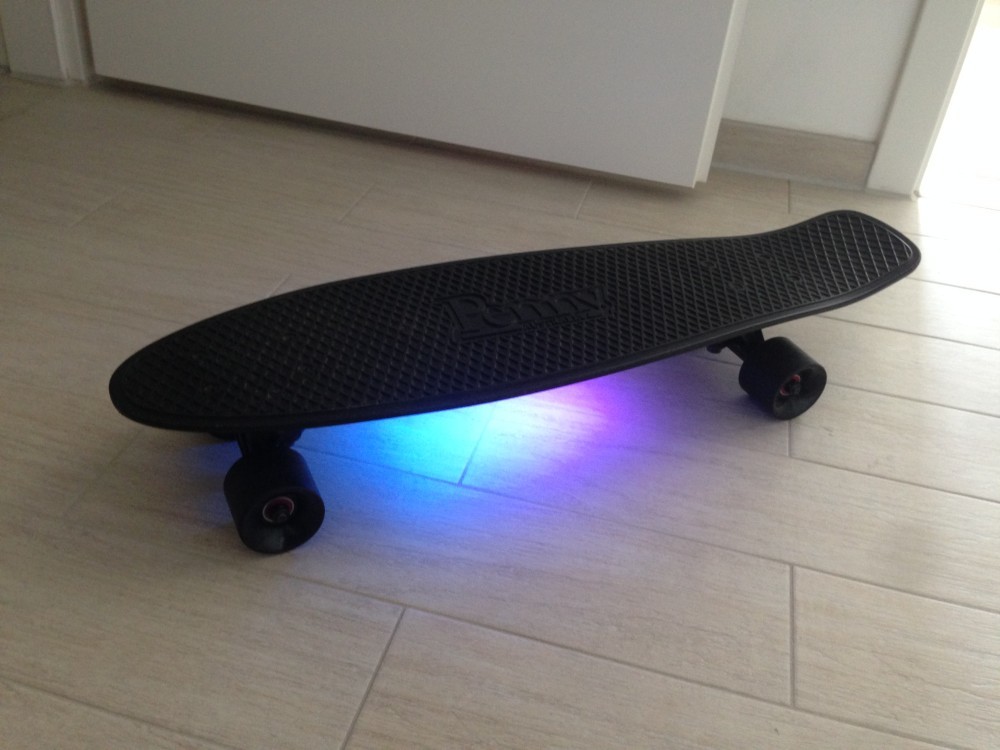
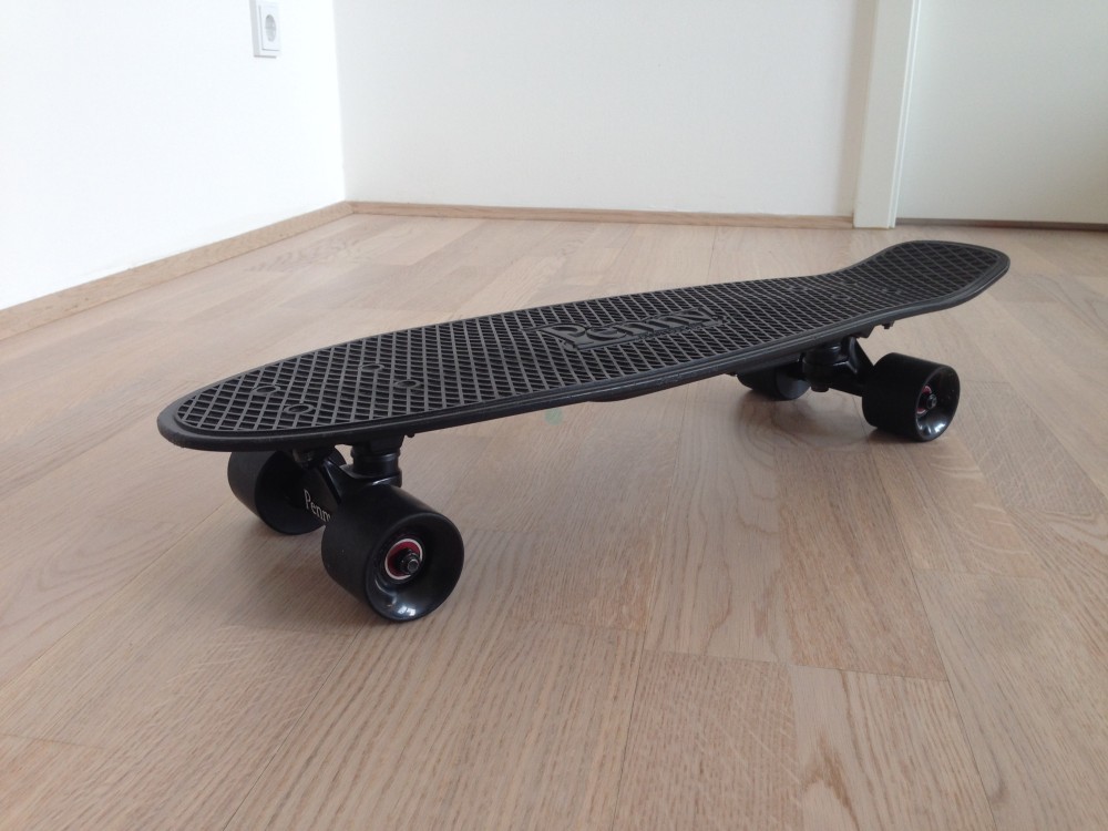
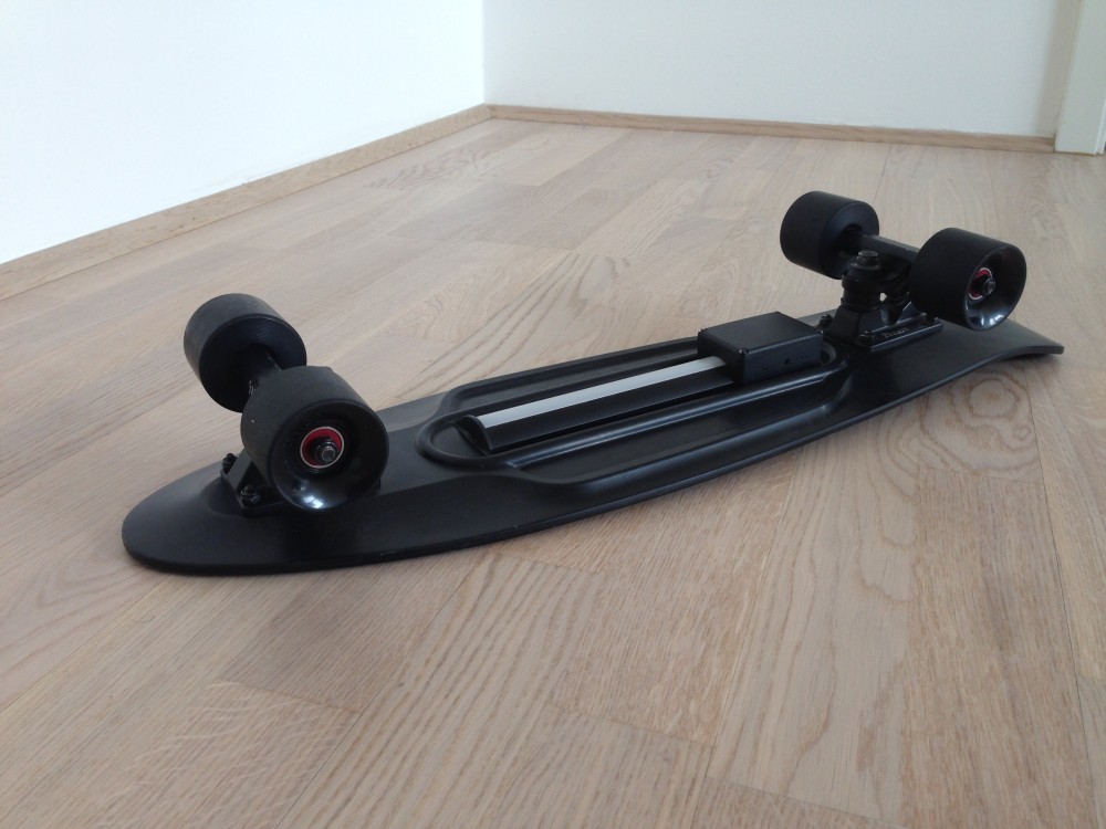
The final Pennyboard 27" Blackout with underglow
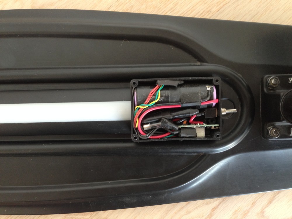
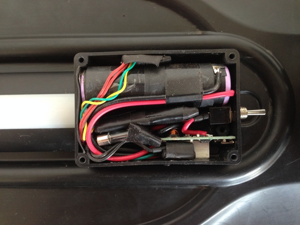
The power circuit
I used the same universal plastic case like last time so I challenged myself a lot because of the small volume of the box to fit every component in. I bought a small power bank with just one 18650 cell in it. It was in a round aluminum case and it was pretty hard to get the glued battery cell out without damaging it (lithium cell + damage = dangerous). Finally I used a Dremel to open it really really carefully (which took a while). I only damaged the outer plastic foil so it wasn't a big issue. The power bank control board has three small white LEDs to indicate the battery level.
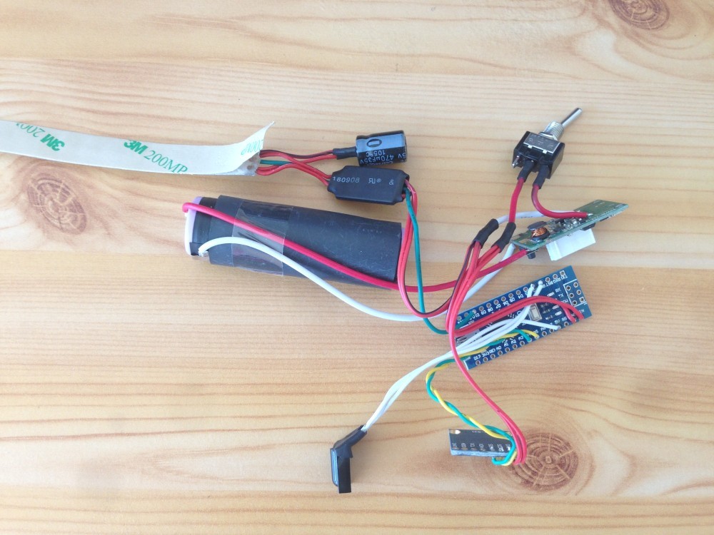
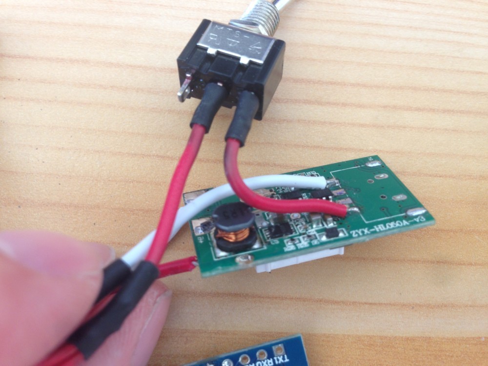

One disadvantage of this power bank model is the fact that it needed to be “activated” by a button click. It does not provide power automatically. So every time I want to start the board I need to click the small button first and after that the main switch to finally power the controller and the LEDs.
I also used a simple 20x50mm fuse to protect the circuit from fatal malfunctions.
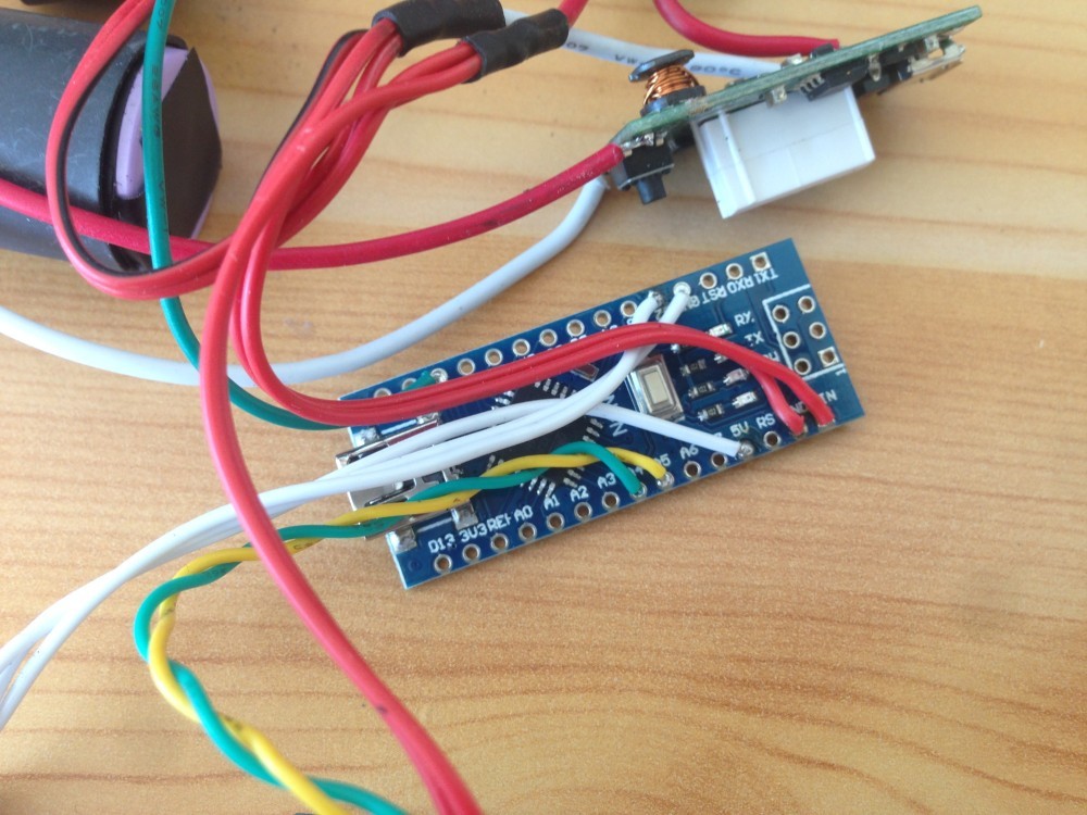
The micro controller
I used a Arduino Mini clone as micro controller because it has a USB serial chip on-board. This draws the battery even if you don't have connected anything, but it provides the comfort that you are always be able to flash it without looking for a programmer and handle a lot of wires).
The high power LED strip
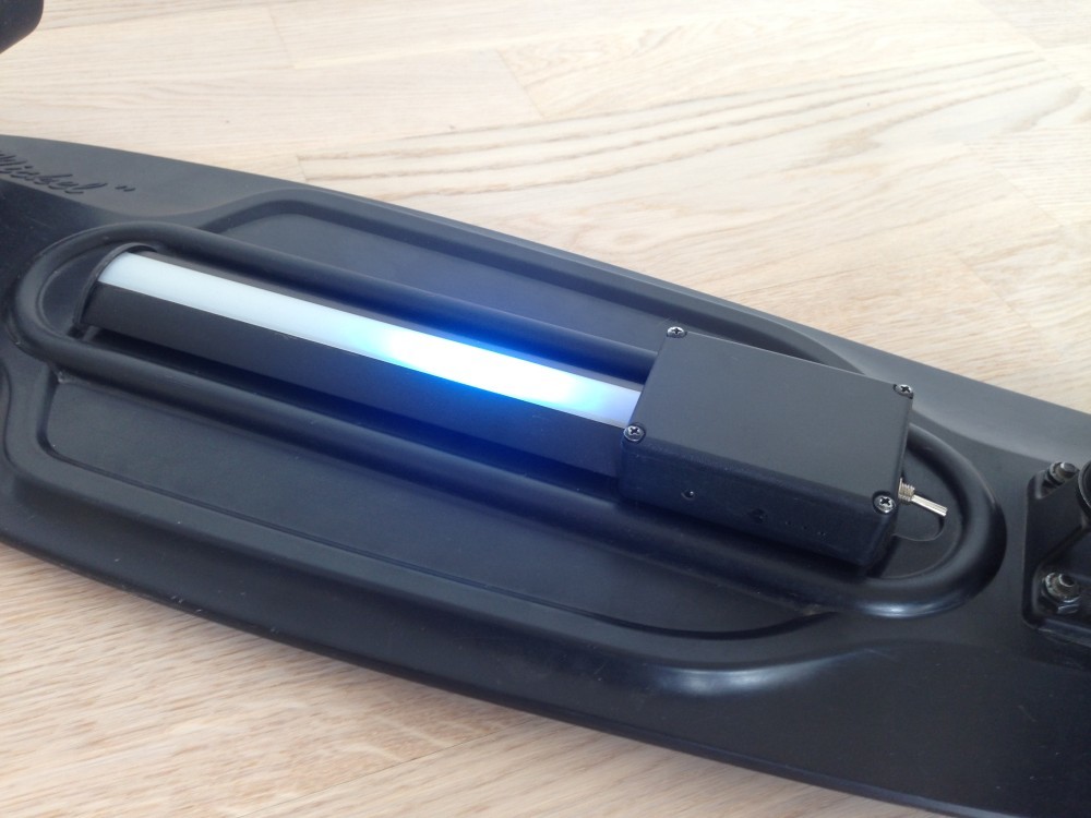
I used a WS2812 LED strip again but this time I used the 144 LEDs per meter edition to have maximum light per length because my plan was to have only one strip in the middle of the board. So I will have a lot shorter strip length (compared to my previous mini cruiser underglow project) which I tried to compensate a bit. This time I used a proper protection circuit from LED Studien to protect my WS2812 pixels.
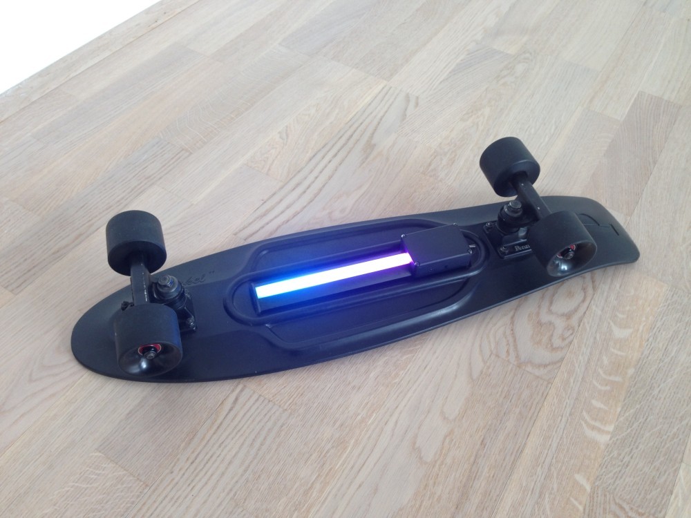
The LED strip emits a huge amount of light especially at night
The accelerometer MPU6050A
I also included the MPU6050A sensor to detect pushes and brake motions - inspired by the following videos:
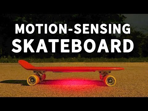
DIY pennyboard with motion detection

LED snowboard with motion / trick detection
But to be honest my final result is not that good as the projects in these videos. It is quite hard to detect the motions with raw sensor data on that low level (despite I used some math to combine the accelerometer and the magnetometer to get more accurate data). The hard hits the board let the sensor freak out and resulted in a lot of spike values. It would cost a huge amount of time to calibrate and tweak it to have a good motion detection. And I was not that motivated to do that. So the motion detection feature of the board is not really a sales pitch :-)
The command channel (IR receiver)
This time I avoided to use an ESP8266 because of its power draw. I only have one 18650 lithium cell with around 3000mAh to power 25 high power LEDs so I didn't want to waste energy because of Wi-Fi. But to be able to still send commands to the controller (to set scenes/animations) I included a common IR receiver.
There was a small problem with “IRremote” library I used together with the “Neopixel” library from Adafruit. Because both libraries use interrupts and thus timing is a important thing, they interfere each other which resulted in random IR codes I received. But luckily there is a easy fix for this problem.
So instead of the loop like:
void loop()
{
    // Do some Neopixel stuff
    neopixelStrip.setPixelColor(0, 0xFFFFFF);
    neopixelStrip.show();

    if (irReceiver.decode(&irReceiverResults))
    {
        const long decodedValue = irReceiverResults.value;

        // Do stuff with decoded value

        irReceiver.resume();
    }
}
You just add a check if the IR receiver is “idle” to avoid that the Neopixel library interfere the IR library:
void loop()
{
    if (isIRReceicerIdle())
    {
        // Do some Neopixel stuff
        neopixelStrip.setPixelColor(0, 0xFFFFFF);
        neopixelStrip.show();
    }

    if (irReceiver.decode(&irReceiverResults))
    {
        const long decodedValue = irReceiverResults.value;

        // Do stuff with decoded value

        irReceiver.resume();
    }
}

bool isIRReceicerIdle()
{
    return (irReceiver.decode(&irReceiverResults) || irReceiverResults.rawlen == 0);
}
A big thank to Sam Curren that found the solution for this problem.
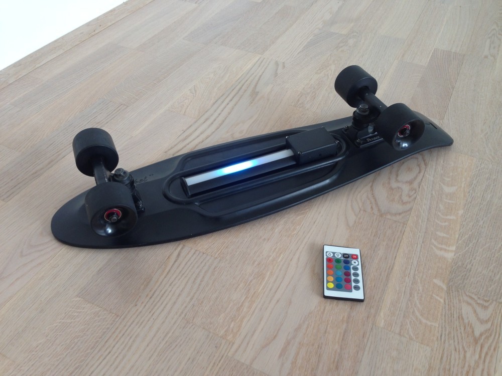
For remote control I used a remote which I had laying around from a common LED strip controller. It was small, nice looking and perfect with its colored buttons and other effect buttons (off/on, some effects, dimming) to use - just read out the IR control codes of the buttons with the Arduino and freely allocate it for any purpose.
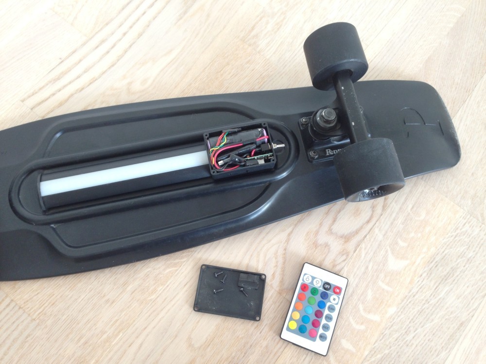
I used a simple remote from LED strip controller to control the board
The software
The software is not that special except of two parts:
- the motion detection part (which does not work well)
- the non-blocking animations
The non-blocking animations were needed to have a controller which is always responsible to receive IR commands. When you write LED animations is is really easy to do it with help of the delay() call, which will cause the CPU to do absolutely nothing while this delay time. Because it is a singlecore microprocessor, the hole “system” is blocked, if the IR receiver receives some commands or the accelerometer has new data, the microprocessor would miss them all in the delay time. So by using delay() it is easy to create animations but has also big disadvantages.
But there is a solution for the problem: You simply use the time counter millis() or micros() of the micro controller and check in every loop if enough time passed to do an animation update. If so also save the current counter value for the next check. If still not enough time is passed, just do nothing. There are a lot of tutorials on the internet that uses this method, so I won't explain it here more detailed. So the challenge was to rewrite some nice looking Neopixel animations like the rainbow to be non-blocking. I also wrote a pretty cool “laser scanner” animation that looks like the scanner of K.I.T.T. in “Night Rider” - but see yourself:
The night rider K.I.T.T. laser scanner animation
Nice REDS bearings
Finally I replaced the pretty decent original Penny bearings with some nice REDS that fits great to the black wheels:
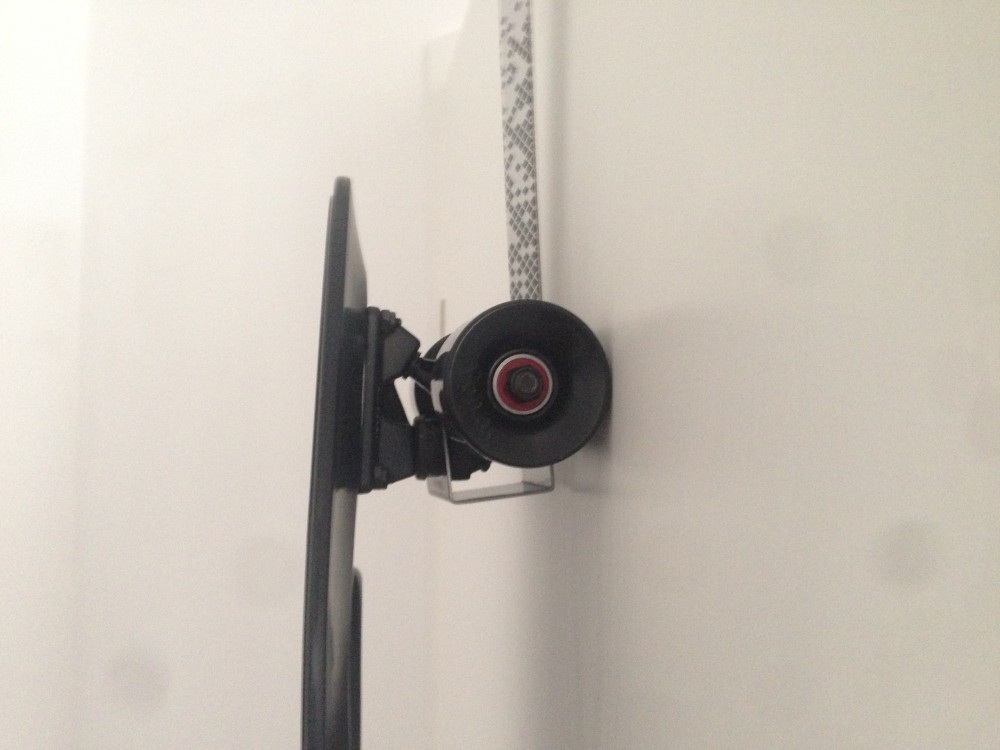
The nice looking REDS bearings fits perfectly to the black wheels
Final impressions
Finally here are some more images of the project:
The firmware
The firmware is available on Github. Just flash it via the Arduino IDE to your board.