Smart MQTT cinch audio channel switcher for Home Assistant integration (Update)
Written by Bastian Raschke.
Published 2019-06-22 in the category Smart Home.
This project tackles an issue I had since I have a central sound system but multiple input sources (my computer, my Android TV, etc.). I used a Hama cinch input switcher (the model with the great name “Game AV Selector Deluxe”) to handle that. But I was really annoying to manually switch the channels - for example I already sit on my couch and forgot to switch to the Android TV channel and so I needed to stand up again for that...
This big first world problem needed to be solved of course!
Here you see the final project:
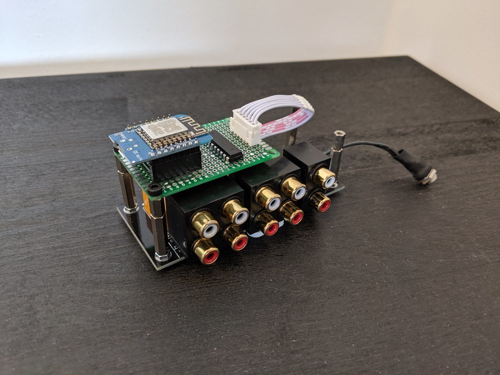
The final MQTT cinch audio channel switcher
Build it
I bought an audio cinch relay board from China to save some time. You can find it with the keywords “audio input selector” - mine seems to be from the brand “AIYIMA”. Be sure you don't by the amplifier version! The board costs around 10-15€. After I received it, I noticed it has a 12V AC power input (no idea why). Because my plan was to power it with a small 12V DC power supply I did some modifications.
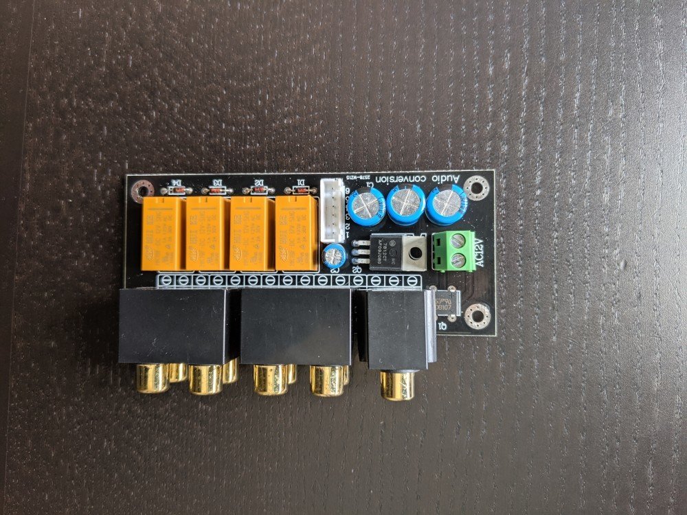
The unmodified audio input selector board from AIYIMA
Power saving modifications
I removed the full bridge rectifier, two of the big smoothing capacitors, the 7812 linear regulator and its small capacitor. The modifications are theoretically not necessary: the DC input would stay DC of course but the linear regulator drops the voltage a bit - the 12V would become around 11V, but the main problem is extra current draw of the linear regulator that is absolutely not needed. So I removed all that unnecessary stuff (I left one big smoothing capacitor because it is a good idea to have at least one).
Measured power consumption
The idle current draw of the board before modifications was around 18,5mA - after the modifications it draws only around 0,085mA (including the control board but without Wemos D1 mini). This means it draws around 217 times less energy! These savings sounds great, but they are actually insignificant compared to the additional drawings of the other components that are necessary for normal operation: around 16,5mA for a relay to hold its state, the Wemos D1 mini with 50-150mA (according to load/software/WiFi state etc.). All in all the complete system consumes around 150mA in average which are around 2 Watts and not that much at all.
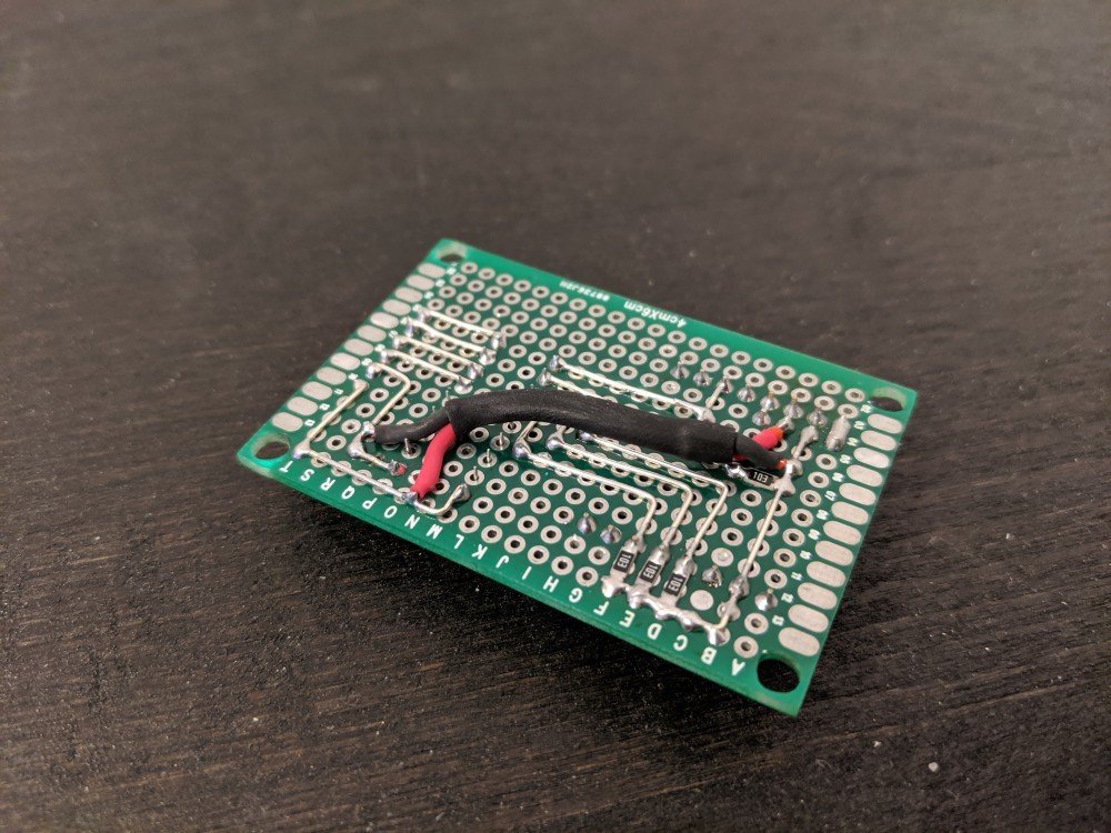
Next I also removed the green power terminal and added a fuse holder to the free space instead. Than I added some silver wires to make the board working again dispite the removed components:
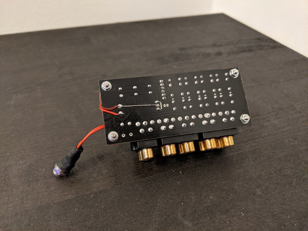
The bottom side of the audio input selector board with some modifications
The control board
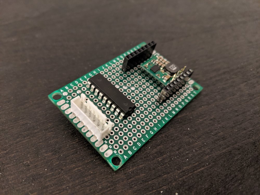
Next I build the control board with only a few components:
- Wemos D1 mini ESP8266 + headers
- PNP transistor array (min. 4 channels, e.g. UDN2981)
- Efficient 3,3V switching regulator (Pololu D24V10F3)
- 10kOhm SMD resistors
The control board is connected to the relay board via a 6 wire ribbon cable (12V, GND, CH1, CH2, CH3, CH4). The 12V powers the UDN2981 and the D24V10F3, the 3,3V output of the D24V10F3 is directly connected to 3,3V pin of the Wemos D1 mini. The first four inputs of the UDN2981 are pulled-down via the 10kOhm resistors and connected to 4 output pins of the Wemos D1 mini (D1, D2, D3, D0). The four outputs of the UDN2981 are connected to the relay board channels. Here you see the schematics (designed with BlackBoard from Matthias Pueski):
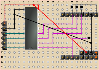
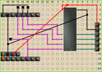
The control board schematics - top side and mirrored bottom side
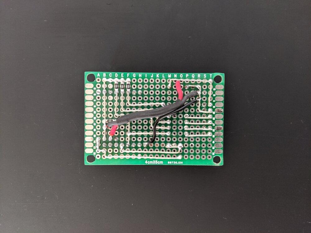
The finished control board:
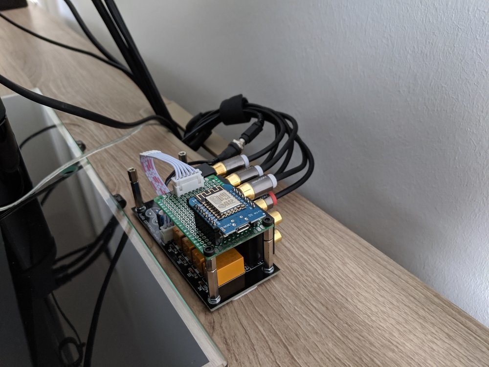
Finally I added a 6mm DC jack, shorted the ribbon cable, added some spacers for a board-to-board inter-connection, added a 250mA fuse and finally connected the two boards. Et voilà:
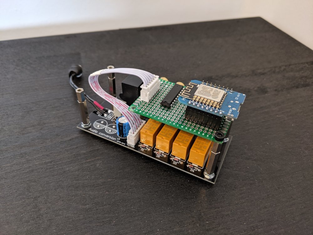
The final project (relay board connected to control board with Wemos D1 mini)
Software setup
Flashing the firmware
The firmware is available on Github:
Change the desired values in src/Firmware/sketches/Production/config-sample.h and rename it to src/Firmware/sketches/Production/config.h. Than flash it to the Wemos D1 mini via the Arduino IDE.
Home Assistant configuration
Put the following configuration blocks to the top level of your Home Assistant configuration file configuration.yaml:
input_select:
  soundswitcher:
    name: Soundswitcher
    options:
      - 1
      - 2
      - 3
      - 4
    initial: 1
    icon: mdi:speaker

automation:
  - alias: "Get soundswitcher state"
    trigger:
      platform: mqtt
      topic: "/soundswitcher/api/1/id/AAAABBBB/state/"
    action:
      service: input_select.select_option
      data_template:
        entity_id: input_select.soundswitcher
        option: "{{ trigger.payload }}"

  - alias: "Set soundswitcher state"
    trigger:
      platform: state
      entity_id: input_select.soundswitcher
    action:
      service: mqtt.publish
      data:
        topic: "/soundswitcher/api/1/id/AAAABBBB/command/"
        payload_template: "{{ states('input_select.soundswitcher') }}"
This results to the following Home Assistant UI:
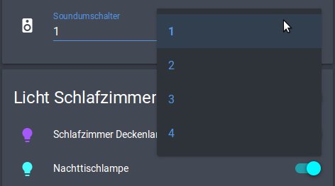
The sound switcher integrated in Home Assistant
Audio installation
Finally I installed the project to my audio system:
The final project connected to my audio system
No more hassle need to stand up and manually change the audio channel :-)
Update 2020-09-20
Always when I had problems with my MQTT broker (e.g. the micro SD card of the Raspberry Pi died), I was not able to switch my audio channels in any way except manually rewiring the audio cables. The subjection to a working broker motivated me to add a manual possibility to switch channels via physical button.
Here you see the updated schematics:
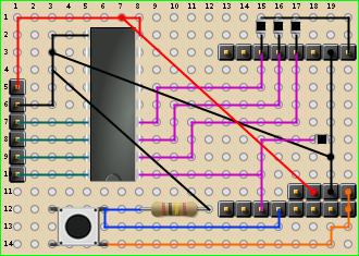
The updated control board schematics with button and 10kOhm DIP pull-down resistor
The updated control board:
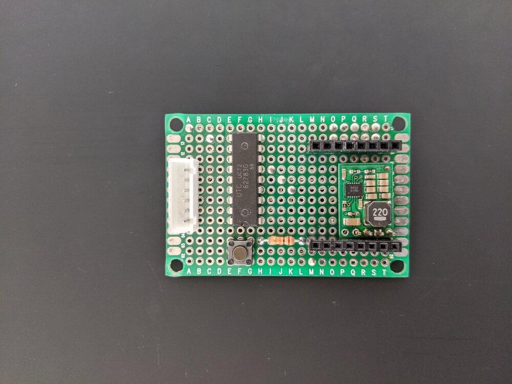
Now the audio channels can be switched directly via the button.
Tags: ESP8266, DIY, Smart Home, Home Assistant