CAN bus (AsysBus) component for smart home system “Home Assistant”
Written by Bastian Raschke.
Published 2018-05-20 in the category Smart Home.
The AsysBus software was developed by Florian Knodt and was originally derived from a software called iSysBus. Basically the AsysBus is a firmware for AVR devices (e.g. the Arduino platform) to create a cheap and robust classic bus network for embedded devices. The communication is realized via CAN bus that is mostly popular in automotive industry. So you can easily create cheap nodes to control lights, RGB(W) light strips, wall buttons or any other possible device to interact with your smart home.
But without integration of my other smart home components (e.g. my Philips Hues) that system would not make a lot sense for me. So I created a component to use AsysBus in the popular smart home software Home Assistant.
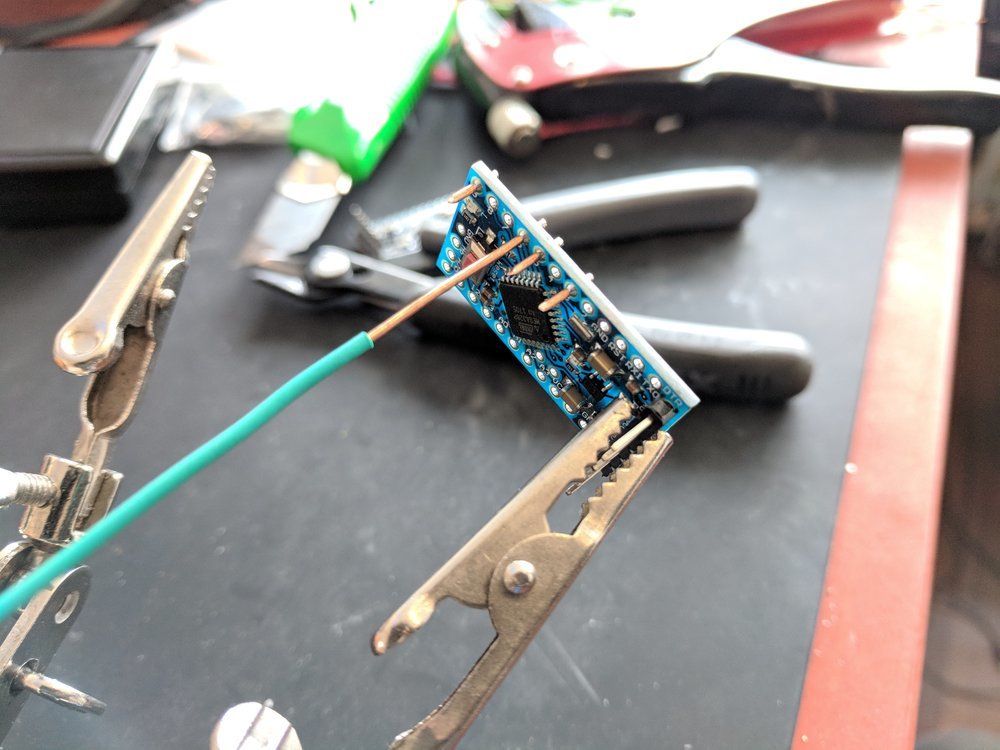
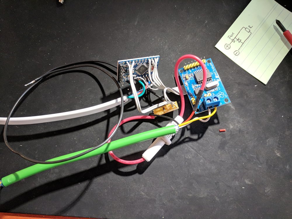
Each AsysBus node consists of a low power Arduino Pro Mini (Clone)
No OpenHAB anymore, but Home Assistant
Before, I used the software OpenHAB to have only one interface to control all of my smart home devices. But because OpenHAB is written in Java and runs extremely slow on a Raspberry Pi (at least on the Raspberry Pi 3 it takes around some minutes to fully boot up), is not that easy extendable (for me) and looks really old fashioned, I searched for alternatives: Unfortunately OpenHAB 2 is even more bad, because they use an inconsistent way for configuration (in my opinion): In OpenHAB 1 everything was configured via text configuration files which I pretty liked - transparent and easy to work with. But version 2 uses a crude “hybrid” approach, so some configuration is stored in a “black box” database somewhere and some configuration is still done via text files. I really hated that fact, so OpenHAB 2 was no alternative for me and I had to research a bit more.
Fortunately I found the Home Assistant project which is open-source, also supports a huge amount of smart home devices, is written in modern Python 3 and finally has a really big community. Also the look and performance is really nice - on a Raspberry Pi 3 the full boot takes under one minute.
AsysBus pros and cons
But back to AsysBus. The classic wired network approach has some pros and cons you should know:
Pros
- wired communication, no data is ever send via the air and could be wirelessly sniffed by an attacker
- because of the CAN bus, the communication is really robust
- cheap nodes (only Arduino Pro Mini and a MCP2515 CAN bus module required)
Cons
- a wired bus infrastructure must be created first
- “old school” bus topology required for CAN bus (not that flexible as ethernet for example)
- each node needs wiring to the bus
To sum up, a bus network for your smarthome only worth if you are a) paranoid b) have fun with nerdy bus cables in your apartment or c) need a robust and very reliable network for some case.
CAN bus topology
The nodes are connected with classic bus topology via a KNX cable (which is cheap, has the two required data wires and two power wires). To avoid having a small power supply for each node, I powered the nodes via the power wires of the KNX cable by a bigger power supply. Also one powerful high quality power supply is more efficient that a ton of small, cheap (and probably inefficient) power supplies for each node.
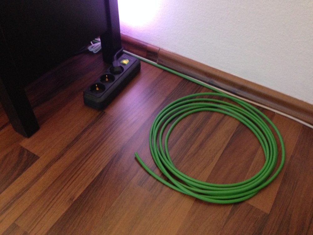
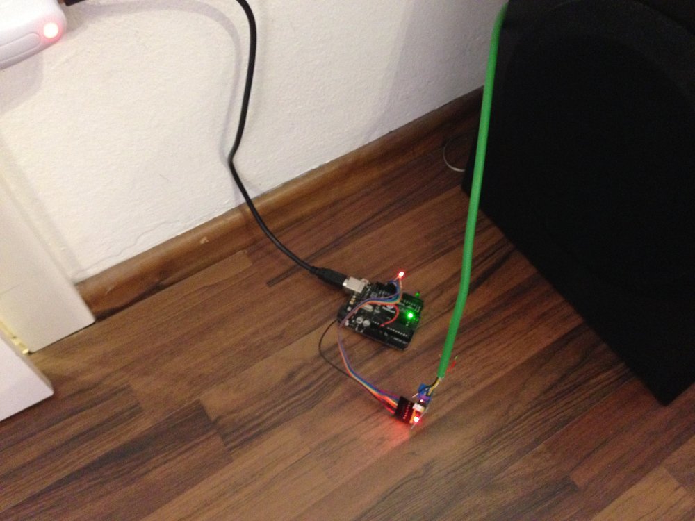
Here you see the first test wiring across my room - one the first photo, the node is still not connected
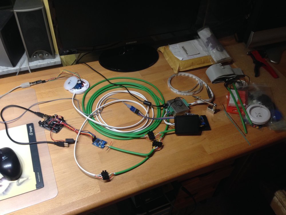
My experimental development network :-)
My AsysBus nodes
I created three types of nodes for my use. A bridge node, a wall switch node and a RGB(W) light node.
Bridge node
The bridge node is the bridge from the AsysBus/CAN bus network to Home Assistant. It is needed to connect the bus network to the device that runs Home Assistant (e.g. a Raspberry Pi). Fortunately the AsysBus software already provided a “routing” feature, which uses some abstraction of the communication interfaces: So for the CAN bus communication it just implements an abstract interface. Another implementation of that interface is the UART interface. So all communication data from one interface (e.g. CAN bus) is automatically routed to the other interfaces (e.g. UART). Basically the bridge node provides a serial port and reads the data on the CAN bus and writes it to the serial port and reads data on the serial port and writes it to the CAN bus.
Wall switch node
This node is basically a simple wall switch that allows you to trigger actions when touching it. So you don't need to get your smartphone out to switch on a light scene for example. My design uses a capacitive touch sensor for touch sensing and a LED for touch feedback (like in my other smart button project). Additionally I added a small vibration motor to add some more feedback.
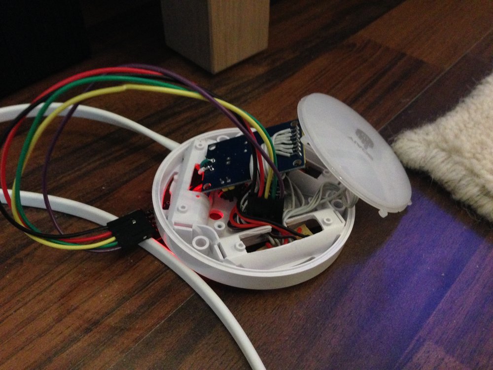
An opened AsysBus wall switch node
The vibration motor of course is not directly driven by the micro controller because it draws too much current. Instead a transistor, a fitting resistor and a flyback diode is used to switch the motor without damaging or destroying the micro controller. I used a vibration motor from a old one-way teeth-brush (alternatively extract it from an old phone).
RGB(W) light node
The light node simply controls a RGB(W) LED light strip.
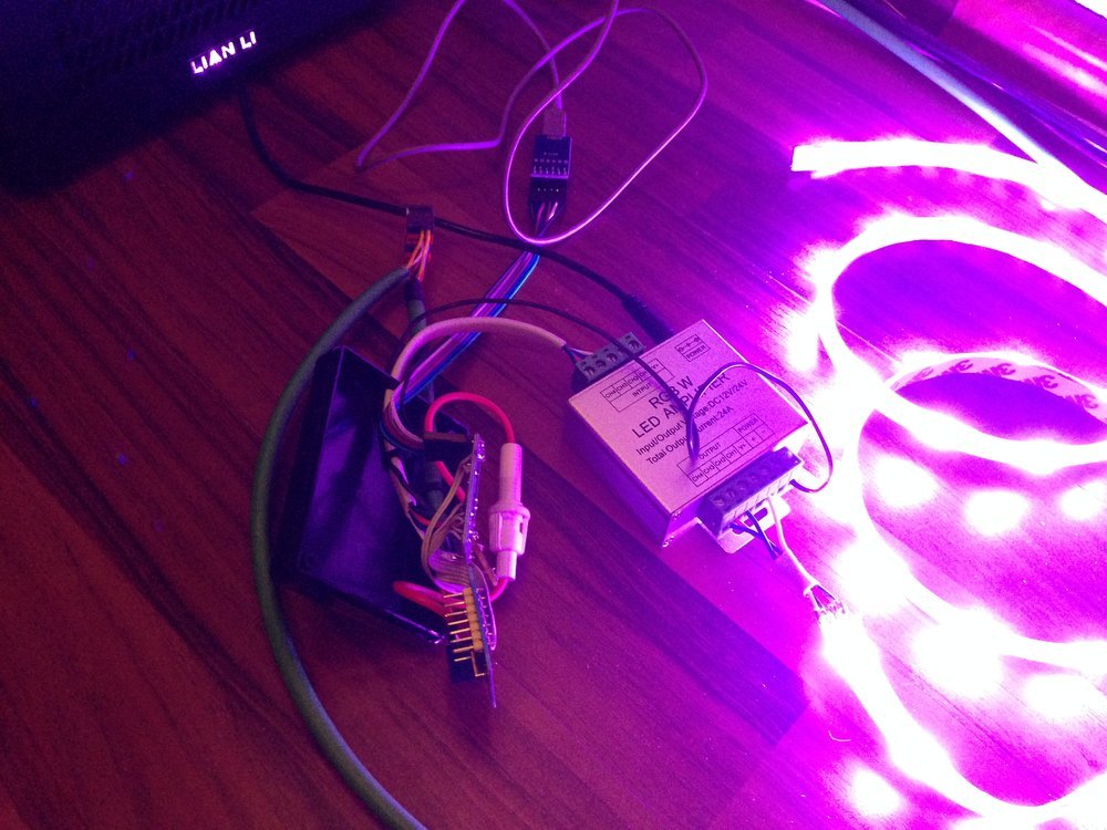
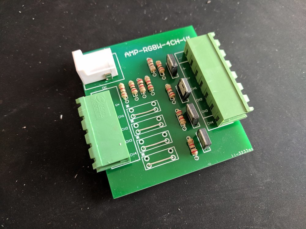
A light node without any housing and a simple test setup with RGB LED strip
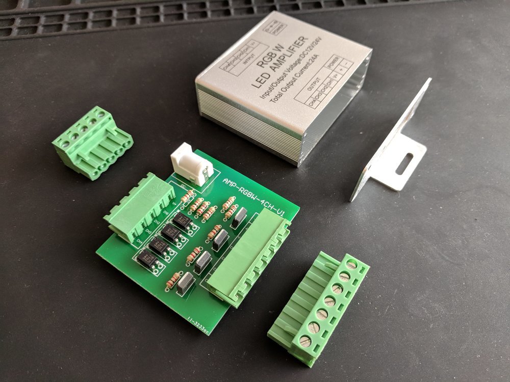
The light strip is not directly powered by the node because of the huge amount of current a LED light strip draws: I bought some “RGB W LED amplifier” cheap on Ebay from China and modified them to act as a LED switching unit: The PWM signal of the micro controller directly switches the high power MOSFETS of the LED amplifier that switches the LED channels. To modification was really easy: I just removed the opto-copplers and replaced it with direct wires:
 >
>
All 4 color channels of the LED strip are connected to output of the “amplifier”. The input channels are directly connected to the micro controller PWM capable digital output pins.
Home Assistant component
So we have the node hardware, the firmware for the nodes and the bridge to connect the CAN bus to Home Assistant. But one last component is still missing to let the system work:
The Home Assistant component that understands the data from the bridge node and provides a platform for Home Assistant to include the nodes as normal switches or lights.
Installation
Because the component is not shipped by stock Home Assistant (I still didn't opened a pull request and I'm also not sure if it is relevant for the most people), you need to use the “custom_components” installation method of Home Assistant. You simple copy the files of the AsysBus Home Assistant component into a directory called custom_components in your configuration directory (by default ~/.homeassistant/):
$ cd ~/.homeassistant/
$ mkdir -p ./custom_components/
$ git clone https://github.com/bastianraschke/asysbus-home-assistant-component ./custom_components/
Configuration
Now you need to connect your flashed bridge node to the device you running Home Assistant on. It should appear as a serial device, e.g. /dev/ttyACM0.
Than put the following configuration block to the top level of your Home Assistant configuration file ~/.homeassistant/configuration.yaml:
asysbus:
  serial_port: /dev/ttyACM0
  baudrate: 11520
If the serial ports differs, you need to change it of course.
Now it is time to include the switch and light nodes into your setup. For example you have two light nodes with node ids 0x03E8 (supports RGBW) and 0x03E9 (supports only RGW) and a switch node with the id 0x07D0. First you add the following configuration to the light block of your Home Assistant configuration:
- platform: asysbus
  id: 0x03E8
  name: "Asysbus light 1"
  type: "RGB"

- platform: asysbus
  id: 0x03E9
  name: "Asysbus light 2"
  type: "RGBW"
Afterwards you add the following block to your switch block:
- platform: asysbus
  id: 0x07D0
  name: "Asysbus switch 1"
After a restart of Home Assistant, the components should included in your setup. Otherwise look for error messages in the log (mostly wrong serial port) and fix the problem.
Usage
Now you can use the components the same like Philips Hues lights etc. The light nodes supports most features of Home Assistant (e.g. delayed transitions). And the switch could be used to trigger scenes for example.
Firmware for the nodes
The firmware for the nodes is available on Github:
Software (Home Assistant component)
The Home Assistant component is available on Github:
Tags: DIY, Arduino, LED, Smart Home, Security, Home Assistant